
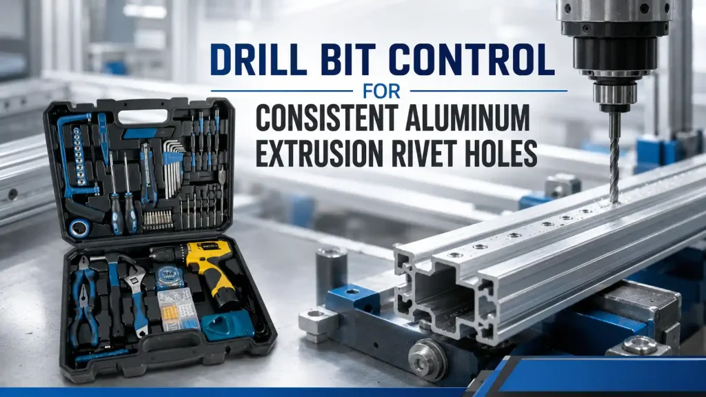
Aluminum extrusion programs often contain hundreds of apparently simple rivet holes, yet a small change in hole diameter, position, burr height, or wall distortion can interrupt assembly across an entire batch. Bestwin manufactures drilling tools for OEM, distributor, and production programs, and our factory sample review treats each Drill Bit as part of a controlled hole-making process. The approved result connects the extrusion alloy and temper, wall geometry, fixture datum, machine interface, cutting condition, hole quality, tool-life rule, marking, and repeat-order record.
For enclosure producers, window and door system factories, transport-equipment builders, solar-frame fabricators, and contract manufacturers, the commercial requirement is not simply a nominal bit size. The Drill Bit must produce a hole that accepts the specified rivet consistently without enlarging the assembly clearance, deforming the profile, or creating burrs that interfere with fit and finish.
Quick Answer
A Drill Bit produces consistent aluminum extrusion rivet holes when its diameter, point geometry, flute finish, edge condition, shank, and runout are matched to the extrusion wall, alloy, surface treatment, machine, fixture, speed, feed, lubrication, and breakthrough condition. Approval should use the actual profile and rivet, measure the first and later holes, and define a tool-change limit before burr growth or diameter drift affects assembly.
The hole drawing should control more than diameter. Position, roundness, entry and exit condition, wall deformation, spacing from an edge or internal rib, and the fit of the installed rivet all matter. Drill Bit selection is reliable only when those requirements are tied to a repeatable factory test.
Confirm the Rivet Joint Before Specifying the Drill Bit
The rivet drawing establishes the functional hole range. A blind rivet, structural rivet, threaded insert, or another fastener system can require a different clearance and surface condition. The extrusion drawing adds the wall thickness, internal void, rib location, coating, edge distance, and positional datum. A Drill Bit specification that begins with diameter alone leaves too many assembly variables undefined.
The production record should identify whether the hole passes through one wall, two separated walls, or a reinforced section. Drilling across a hollow profile creates two breakthrough events. If the tool is not aligned, the far wall can receive an offset or elongated hole even when the entry looks correct. When the profile is later riveted to a bracket or sheet, that hidden error appears as forced alignment, poor clamp-up, or variable fastener setting.
The joint should be evaluated with the real mating part and the specified rivet. A gauge pin can confirm size, but it cannot show whether the rivet seats, expands, and clamps as intended. The Drill Bit sample result therefore includes dimensional evidence and an assembled-joint check.
Table 1. Inputs That Define an Aluminum Extrusion Rivet-Hole Program
| Program input | Required project detail | Effect on the Drill Bit and process |
|---|---|---|
| Extrusion material | Alloy, temper, supplier, wall thickness, lot variation | Changes cutting load, chip behavior, burr formation, and life |
| Profile geometry | Single wall, double wall, hollow section, rib, edge distance | Controls support, reach, breakthrough, and alignment |
| Surface condition | Mill finish, anodized, painted, powder-coated, protected face | Changes cosmetic acceptance and coating-damage limits |
| Joint design | Rivet type, nominal body size, grip range, mating part, access | Establishes functional hole size and assembly verification |
| Hole definition | Diameter, position, roundness, perpendicularity, burr and chamfer limits | Converts a nominal size into measurable acceptance criteria |
| Equipment | Hand fixture, drill press, pneumatic spindle, CNC, transfer line | Determines shank, holder, runout, speed, feed, and repeatability |
| Cooling and chips | Dry, mist, fluid, extraction, chip collection, cleaning | Influences built-up edge, finish, contamination, and downstream assembly |
| Supply program | Batch size, holes per part, line rate, resharpening rule, packing | Determines life target, sampling frequency, and lot traceability |
Treat the Extrusion as a Structured Workpiece
An extrusion is not a flat sheet. Its walls, voids, ribs, corners, and varying section thickness change how the Drill Bit enters and exits. A thin outer wall may deflect under thrust, while a nearby rib may increase stiffness. A tool can cut cleanly through the first wall and then move as it crosses the hollow space before contacting the second wall.
Fixture support should be located near the drilling zone without crushing the profile. The production datum must remain the same datum used on the drawing. If operators position from a cut end whose length varies, hole location can drift even while the Drill Bit and machine remain unchanged. A nest, stop, or locating feature should control the profile in the directions that affect the riveted joint.
For long profiles, straightness and twist also influence location. The fixture may need several supports while allowing chips to escape. A rigid clamp at one point cannot correct a profile that lifts or rolls at the drilling station. The acceptance sample should represent the actual cut length and support arrangement.
Control Runout Before Adjusting Cutting Parameters
Runout enlarges the swept path of the cutting edges. A nominal 5 mm Drill Bit can produce an oversized or lobed hole if the shank, chuck, collet, spindle, or adapter does not rotate concentrically. Changing speed or feed will not correct a mechanical centerline problem.
Runout should be checked at a consistent location and with the same holder used in production. The machine record should include spindle condition, holder identity, clamping length, and any adapter. A tool that performs well in a laboratory holder may not reproduce that result in a worn production chuck.
Point symmetry matters as well. If one lip carries more load, the Drill Bit can pull sideways, generate an uneven burr, and wear faster on one edge. The used tool provides useful evidence: balanced wear supports the setup, while one-sided polishing or chipping suggests an alignment, grinding, or clamping problem.
Match Point and Flute Behavior to Aluminum Chips
Aluminum can form long, adhesive chips. When material builds on the cutting edge, the effective geometry changes. The hole wall may smear, the diameter may move, torque may rise, and the exit burr may grow. A Drill Bit for this program needs an edge and flute condition that continues to cut and evacuate chips through the intended cycle.
Material direction, heat treatment, point geometry, web condition, flute finish, and surface treatment must be evaluated together. A bright appearance or coating color does not prove compatibility. The approval test should show the chip form, hole wall, torque or load trend where available, and the edge condition after a defined number of holes.
Bestwin’s factory can use project samples to compare Drill Bit constructions, but the final direction remains tied to the declared extrusion and operating window. If the customer changes the alloy, temper, anodizing, lubricant, or wall thickness, that change should be reviewed before the original life target is reused.
Establish a Stable Speed and Feed Window
One demonstration hole does not define a production window. Speed, feed, pecking, dwell, lubrication, and chip clearing interact with the Drill Bit and the profile. Too little feed can increase rubbing and heat. Excessive feed can deflect a thin wall, overload the edge, or create a heavy exit burr. A long dwell at breakthrough can enlarge the hole without improving it.
The useful process window is a range that remains stable across normal machine and material variation. It should be confirmed on the actual equipment at the expected line rate. If the operation uses a hand-fed fixture, the method should include a physical stop or controlled guidance where practical, because operator feel alone is difficult to reproduce across shifts.
For automated equipment, the program identity should preserve spindle speed, feed approach, breakthrough reduction if used, retract behavior, and any chip-clearing cycle. A Drill Bit change cannot be separated from those values if the hole result was approved as a combined process.
Watch the Transition Into a Second Wall
When a Drill Bit crosses a hollow profile, it loses support before meeting the far wall. The tool may deflect, and chips from the first wall can remain in the void. The far-wall entry therefore deserves its own inspection, especially when both holes guide the same fastener or locate a mating part.
A guided fixture, suitable working length, controlled feed, and sound spindle can reduce the risk. If a bushing is used, its clearance, wear, and distance from the surface become part of the process record. A worn bushing can make a good tool appear inconsistent.
Define Burr Acceptance at Both Faces
Entry and exit burrs have different causes and consequences. An entry burr or raised edge may affect a visible anodized surface. An exit burr can prevent a bracket from seating, damage a cable, contaminate an enclosure, or interfere with the rivet head or mandrel. The Drill Bit approval should define where burrs are measured and whether a secondary deburring step is permitted.
A process that depends on heavy deburring can hide poor drilling stability. Deburring also adds labor, changes the hole edge, and can damage a finish. Where a light controlled edge break is part of the design, its tool and limit should be specified separately from the primary hole.
Photographic boundary samples are useful for cosmetic surfaces, but they should be taken under consistent lighting and magnification. Dimensional burr limits can be combined with visual samples when the customer needs both assembly function and appearance. The Drill Bit change point should be set before the burr crosses that limit.
Prevent Wall Deformation and Exit Pull
Thin extrusion walls can dish, stretch, or pull toward the Drill Bit at breakthrough. The final hole may measure within diameter tolerance yet sit in a locally distorted surface. A rivet head then contacts unevenly, and the assembled joint can show a gap or mark.
Support, clamping, point geometry, thrust, edge condition, and breakthrough feed all influence deformation. The inspection should view the surface around the hole, not only the hole itself. A straightedge, profile gauge, optical method, or assembly check can be chosen according to the drawing requirement.
Where the hole lies near an edge, corner, or slot, the remaining material may not support equal cutting forces. The Drill Bit can wander toward the weaker side. Position and edge distance should therefore be checked together on the approved profile.
Protect Anodized and Finished Surfaces
Anodized, painted, or powder-coated profiles introduce a cosmetic and contamination boundary. The Drill Bit should enter without lifting or chipping the finish beyond the agreed limit. Clamps, nests, chips, and handling surfaces must also avoid scratches that could be incorrectly attributed to the cutting tool.
If the part is drilled after finishing, chip collection and cleaning are part of the production route. Chips trapped inside a hollow profile can rattle, damage wiring, or emerge during later assembly. If the part is drilled before finishing, the process must account for how coating changes the final hole and whether masking or post-treatment is required.
The sample record should name the surface condition. Results from mill-finish stock cannot automatically approve a visible anodized part. A Drill Bit that cuts clean base material may still need different entry control to preserve a finished face.
Use Lubrication That Fits the Downstream Process
Lubrication can reduce adhesion and heat, but it can also contaminate bonding, painting, sealing, or assembly. The project should state whether drilling is dry, misted, flooded, or supported by a specific compatible fluid. The amount and application point should be reproducible.
If a Drill Bit requires frequent manual fluid application to pass a sample, the production team should confirm that the same method is realistic at line rate. Residue removal, worker exposure, filtration, and disposal may affect the process decision. For some programs, a slightly different geometry or operating window with a controlled minimal lubricant is more practical than a condition that produces the best single hole but disrupts later operations.
The approved cleaning method belongs in the record when rivets, sealants, adhesives, or electrical grounding surfaces follow drilling.
Measure Hole Function, Not Diameter Alone
Diameter is essential, but a rivet hole also needs position, roundness, perpendicularity, surface condition, and compatibility with the actual fastener. The Drill Bit may produce an acceptable gauge result while an elongated far-wall hole or heavy burr still prevents consistent assembly.
The inspection plan can combine a gauge or dimensional method with profile position measurement and a rivet installation check. For critical joints, the customer may add sectioning, clamp-up review, push-out or pull testing, or another defined joint test. Those requirements come from the assembly design and should not be improvised after the tools are in production.
A neutral overview of the Drill Bit category shows how widely geometry varies, which is why a factory specification should identify the construction and application rather than rely on the category name alone.
Table 2. Rivet-Hole Symptoms and the Evidence Needed for Correction
| Symptom | Likely process areas to review | Evidence to retain | Corrective decision |
|---|---|---|---|
| Hole is oversized or lobed | Runout, point symmetry, holder wear, tool deflection | Tool and spindle runout, hole map, used-edge photos | Correct the centerline before changing nominal diameter |
| Exit burr grows through the batch | Edge wear, feed, wall support, chip adhesion | Hole sequence, burr measurement, edge condition | Set a life limit or adjust the approved cutting window |
| Far-wall hole is offset | Profile support, bushing wear, working length, tool deflection | Section geometry, fixture datum, entry/far-wall position | Improve guidance or fixture control |
| Finish chips at entry | Edge condition, clamping, surface treatment, start behavior | Boundary samples, finish lot, entry photos | Confirm a surface-specific entry condition |
| Wall dishes around the hole | Thrust, breakthrough feed, local support, dull edge | Surface profile and rivet seating result | Add support or reduce deformation before acceptance |
| Chips weld to the flute | Alloy, heat, lubrication, flute finish, chip cycle | Chip form, tool photos, load or torque trend | Change the process/tool combination, not only cleaning frequency |
| Rivet does not seat consistently | Hole size, burr, position, mating-part alignment | Actual rivet installation and joint inspection | Reconnect drilling limits to the joint drawing |
| Life varies by lot | Material lot, heat treatment, grinding, setup, fluid | Batch identity, incoming checks, process record | Separate tool variation from material or machine variation |
Set Tool Life With a Hole Sequence
Tool life should be defined by the result across a sequence, not by whether the Drill Bit is still physically capable of cutting. Record representative holes from the beginning, middle, and end of the target interval. Measure diameter, burr, position where relevant, cycle time, chip behavior, surface condition, and rivet fit.
The stop rule should use the earliest functional limit. If burr height reaches its limit before diameter changes, burr controls the change point. If built-up edge appears unpredictably, the process may need a cleaning or lubrication rule in addition to a life limit. If runout increases because the holder wears, replacing the Drill Bit alone will not restore control.
Used samples should remain connected to their hole count, machine, holder, material lot, and operating condition. This evidence lets Bestwin and the customer compare a later batch with the approved route instead of judging an isolated returned tool.
Connect Factory Sampling to Repeat Orders
As a Drill Bit manufacturer, Bestwin needs a stable reference for material, heat treatment, forming or grinding, surface condition, diameter, shank, point, flute, marking, inspection, and packaging. The approved customer sample adds the application evidence: real extrusion, real machine, real rivet, and real life interval. Together, those records define the repeat-order identity.
Bestwin’s factory review can include dimensional checks, runout, visual edge condition, packaging, and functional drilling on agreed material. The customer production approval still uses its fixture, line, extrusion, and joint criteria. This division keeps the manufacturing record and application record connected without pretending they are the same test.
Change control matters when a supplier updates raw material, heat treatment, grinding equipment, coating, shank marking, or packaging. It also matters when the customer changes extrusion source, alloy, wall thickness, finish, machine, holder, lubricant, or rivet. A Drill Bit supplier is easier to manage when both sides identify changes before they affect assembly, and Drill Bit Suppliers can be compared against the same change-control expectation.
Validate Packaging and Identification
Cutting edges can be damaged before the Drill Bit reaches the machine. Bulk contact, weak separators, corrosion exposure, mixed sizes, and unclear labels can turn a conforming tool into an inconsistent production input. The packaging plan should protect the edge and keep the exact variant identifiable at receiving and at the drilling station.
For set or kit programs, every size and accessory should match the approved list. For factory packs, quantity, inner separation, rust protection, label, barcode, and lot identity may matter more than retail presentation. Packaging should support the customer’s replenishment and tool-control method.
The receiving check can confirm variant, quantity, physical condition, and documentation before tools enter production. A retained package sample helps investigate whether later edge damage occurred in manufacturing, transport, storage, or line handling.
Prepare an RFQ That Can Be Tested
A useful RFQ states the extrusion drawing, alloy and temper, wall thickness, finish, hole diameter and tolerance, position requirement, burr or cosmetic limit, rivet specification, mating part, equipment, holder, speed, feed, lubrication, holes per part, target life, annual quantity, marking, packaging, inspection, and change-control expectations.
Photos are helpful, but a drawing and representative extrusion sample are stronger. The sample should include difficult features such as a second wall, nearby rib, edge location, or visible anodized face. A Drill Bit sample can then be evaluated at the risk points that matter to the production line.
When comparing Drill Bit Suppliers, the quotation should separate confirmed requirements from open assumptions. That prevents an apparently complete price from hiding a different shank, untested wall condition, or unrealistic life claim.
Final Takeaway
Consistent aluminum extrusion rivet holes come from a controlled relationship between the Drill Bit, structured profile, fixture datum, spindle and holder, cutting window, chip control, surface finish, burr limit, rivet joint, and tool-life rule. A nominal diameter does not capture that relationship. The production record must show how the hole is made, measured, assembled, and repeated.
Bestwin can support this process with factory sample preparation and manufacturing records tied to the requested tool identity, while the customer confirms the result on its extrusion and line. For teams reviewing Drill Bit options, the strongest starting package is the profile drawing, joint requirement, machine interface, and representative production sample. That gives Bestwin and other Drill Bit Suppliers a testable basis for quotation, approval, and repeat supply.










 English
  العربية
  Français
  Português
  Português do Brasil
  Italiano
  简体中文
简体中文  繁體中文
繁體中文  日本語
日本語  한국어
한국어  Deutsch
  Español
  Slovenčina
  ไทย
ไทย  Türkçe