
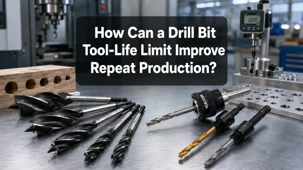
Introduction
In repeat drilling, a tool may produce clean, accurate holes at the beginning of a run but gradually create larger burrs, rougher surfaces, unstable chip flow, or higher machine load. These changes do not always appear at the same number of holes. A Drill Bit may remain effective for a long period in one application and lose performance much earlier in another because the material, hole depth, machine condition, cutting parameters, and cooling method are different.
A practical tool-life limit provides a controlled point for inspection or replacement before quality becomes unstable. It is more useful than waiting for visible failure, but it should not be based on an arbitrary cycle count. The limit needs to reflect the actual drilling operation and the finished-hole requirements. When it is supported by repeatable testing, it can reduce unexpected stoppages, protect workpiece quality, and make tool consumption easier to forecast.
The following sections explain why Drill Bit life changes, which warning signs matter, how a working limit can be established, and how different tool structures should be matched to the material and equipment.

1. Why Does Drill Bit Tool Life Change Between Different Applications?
Tool life is not a fixed property that applies equally to every drilling process. It is a working range created by the relationship between the cutting tool, workpiece, machine, hole geometry, and operating method. Even two Drill Bit products with the same nominal diameter can deliver different results if their point geometry, flute design, carbide grade, coating, or shank accuracy is different.
Workpiece Material and Surface Condition
Material hardness is important, but it is not the only factor. Low-carbon steel, stainless steel, aluminum, cast iron, concrete, timber, and composite panels create different forms of wear. Stainless steel can generate heat and work harden when the cutting edge rubs instead of cutting. Aluminum may form built-up material on the edge when chip evacuation or lubrication is poor. Cast surfaces, scale, abrasive fillers, concrete aggregate, and hard knots in timber can create impact or abrasive wear that shortens Drill Bit life.
Incoming material can also vary between batches. Changes in hardness, heat treatment, thickness, moisture, surface coating, or aggregate content may alter the load on the cutting edge. For this reason, a life figure obtained from clean laboratory material should not automatically be treated as a guaranteed production result.
Hole Depth and Drilling Geometry
A shallow through-hole usually removes heat and chips more easily than a deep blind hole. As hole depth increases, chips must travel farther through the flutes, and coolant or air may have difficulty reaching the cutting zone. Chip packing increases friction, damages the hole wall, and can cause a Drill Bit to seize or break.
Angled entry, cross holes, interrupted surfaces, stacked sheets, and unsupported breakthrough also change the load. A tool entering a sloped surface may deflect before the full cutting edge is engaged. At breakthrough, weak support beneath the workpiece can increase exit burrs or chip the cutting edge. These conditions should be treated separately from uniform drilling in solid material.
Speed, Feed, Impact and Cooling
Cutting speed influences heat generation and wear rate. Feed controls chip thickness and determines whether the edge cuts efficiently or rubs against the material. A feed that is too low may look gentle but can increase rubbing and heat. Excessive feed can overload the lips, damage the point, or create heavy burrs.
For an electric hammer Drill Bit, impact energy, rotation speed, tool diameter, and material density must work together. Excessive pressure does not necessarily improve progress and may increase heat or damage the carbide tip. In rotary metal drilling, coolant concentration, nozzle position, peck depth, and retract distance affect lubrication and chip evacuation. In wood drilling, flute capacity and regular chip clearing become especially important in deep holes.
Runout, Shank Condition and Installation
Runout causes one side of a Drill Bit to carry more load than the other. The overloaded edge wears faster, while the hole may become oversized, tapered, or out of round. Dirt on a taper, a damaged chuck, incomplete shank engagement, or incorrect tightening can make a new tool perform worse than an older tool installed correctly.
Before comparing tool life, the chuck, holder, spindle, guide, and shank should be checked. A stable installation makes performance results more repeatable and prevents machine-related variation from being mistaken for cutting-edge wear.
Table 1. Main Factors That Affect Drill Bit Tool Life
| Factor | Possible Effect | Practical Check |
| Material hardness and abrasiveness | Faster edge or carbide wear | Confirm grade, surface condition and batch variation |
| Hole depth | Heat and chip accumulation | Check flute length, pecking and chip removal |
| Cutting speed and feed | Rubbing, overheating or edge overload | Use an approved operating range |
| Runout | Uneven wear and oversized holes | Inspect chuck, holder, spindle and shank |
| Cooling or lubrication | Heat, built-up edge and poor surface finish | Verify delivery, concentration and nozzle position |
| Impact conditions | Chipping or premature fatigue | Match tool interface and equipment output |
| Breakthrough support | Exit burrs and edge damage | Check backing, clamping and feed near exit |
2. Which Signs Show That a Drill Bit Is Approaching the End of Its Useful Life?
A cycle counter is useful for planning, but it cannot detect every abnormal event. Material inclusions, coolant loss, poor clamping, accidental impact, or chip blockage can damage a Drill Bit before the planned limit is reached. A reliable process therefore combines a routine cycle limit with observable early-change signals.
Changes in Finished-Hole Quality
Hole quality often provides the clearest evidence of progressive wear. Diameter may drift toward the control limit, roundness may deteriorate, and the hole wall may show scoring, tearing, or heat marks. Exit burrs may become higher as the cutting edge rounds and begins to push material instead of shearing it cleanly.
Not every dimensional change comes from the tool. Position error may be caused by clamping, alignment, or fixture movement, while an oversized hole may result from runout. The trend should be compared with machine condition and installation records before the Drill Bit specification is blamed. A go/no-go gauge can provide fast routine feedback, while a bore gauge, optical system, or coordinate measuring machine can support a more detailed study.
Higher Load, Thrust, Heat or Vibration
A worn cutting edge generally requires more force. Depending on the equipment, this may appear as higher spindle power, torque, thrust, servo load, vibration, or adaptive-feed correction. A sharp increase can also indicate chip packing, loss of coolant, or mechanical damage, so the response should depend on the severity of the signal.
A warning threshold can trigger an additional hole inspection. A higher stop threshold should pause the operation before breakage becomes likely. Sound and temperature can support this judgment when they are measured or compared under consistent conditions, but subjective impressions should not replace dimensional checks and defined limits.
Changes in Chip Form and Evacuation
Stable chip formation is a useful reference. In metal drilling, chips that become heavily discolored, unusually fragmented, tangled, or difficult to evacuate may indicate excessive heat, a dull edge, incorrect feed, or a blocked flute. In wood, compacted chips and repeated clogging can increase friction and burn the hole wall. In concrete, reduced progress combined with increasing heat may indicate carbide wear or an unsuitable impact condition.
Chip shape alone is not enough to determine Drill Bit life because material and cutting parameters also affect it. It becomes more useful when recorded together with hole quality, machine load, and cutting-edge condition.
Visible Cutting-Edge Damage
Regular inspection can identify uniform flank wear, chipped lips, built-up material, corner breakdown, damaged margins, worn carbide tips, or heat discoloration. The inspection method should remain consistent. Similar magnification, lighting, cleaning, and viewing direction make photographs easier to compare over time.
Visible chipping, a loose brazed tip, a bent body, a cracked shank, or severe margin damage should be treated as an early-change condition rather than normal wear. Continuing to operate a damaged Drill Bit may affect the workpiece, holder, or machine interface.

3. How Can a Practical Drill Bit Tool-Life Limit Be Established?
A useful limit begins with the required result. A clearance hole may tolerate more variation than a locating hole, threaded pilot, press-fit bore, or visible assembly feature. Burr height, surface condition, diameter, cylindricity, position, and downstream finishing requirements should be identified before the trial begins.
Build a Representative Baseline
The trial should use a representative machine, holder, fixture, material, program, cooling method, and hole geometry. Record the Drill Bit type, diameter, point geometry, flute length, coating or carbide structure, batch identification, and measured runout. First-piece holes should be inspected in detail before drilling continues.
Samples can be checked at wider intervals early in the test and at shorter intervals as the expected wear region approaches. Interruptions, parameter adjustments, material changes, coolant events, and tool removal should be recorded because they may explain unusual results. The trial should stop at a safe quality or wear threshold rather than running deliberately into uncontrolled breakage.
One unusually strong or weak sample is not enough. Repeated trials across several tools and representative batches reveal natural variation. A working limit can then be set below the earliest validated warning region, with an additional margin where a missed defect would have serious consequences.
Separate Planned Limits From Early Triggers
The planned limit is the normal replacement or inspection point used for scheduling. Early triggers protect the process when something changes before that count. Examples include a chipped edge, unacceptable runout, a failed hole gauge, a defined load spike, repeated chatter, unsafe chip formation, or an unexplained increase in cutting time on equipment with adaptive control.
These triggers should be specific enough to produce the same response across different shifts. Photographs, gauge limits, machine alarm values, and sample parts can make the standard clearer than phrases such as “replace when worn.”
Coordinate Sampling With the Warning Region
Inspection frequency should reflect process capability, tool-life variation, measurement speed, and the consequence of a missed defect. If the warning region typically develops over 100 holes but inspection occurs every 200 holes, the plan cannot reliably detect the trend. The interval should become shorter near the expected end of life, or the planned replacement point should be moved earlier.
Wear-trend charts can plot diameter, burr height, load, or another meaningful characteristic against cumulative usage. Regression, EWMA, or CUSUM methods may help when production volume and measurement capability justify them. Conventional control charts require care because progressive Drill Bit wear creates an expected trend rather than a perfectly stable process mean.
Table 2. Example Drill Bit Tool-Life Control Plan
| Control Stage | Inspection Item | Recommended Action |
| Tool installation | Identity, shank, condition and runout | Correct the installation before release |
| First hole | Diameter, position, burr and surface | Establish the accepted starting reference |
| Routine interval | Fast gauge and process-signal review | Continue while results remain stable |
| Warning region | Shorter sampling interval and edge review | Prepare the planned change |
| Early-change trigger | Chipping, poor hole, chatter or load spike | Stop, inspect and contain affected parts |
| Planned cycle limit | Recorded comparable operations | Replace or send for approved regrinding |
| Post-change verification | New first-hole inspection | Restart the monitoring record after acceptance |
Keep Usage Records With the Actual Tool
The usage count should follow the actual Drill Bit rather than only the machine. If a tool moves between stations or returns from regrinding, a local counter may lose part of its history. A tool ID, barcode, traveler, controlled issue record, or suitable digital system can maintain traceability.
The counting rule should also be clear. Completed holes, attempted holes, setup pieces, interrupted cycles, rework, and mixed operations do not always create equal wear. Deep holes and interrupted cuts may need a weighted usage value rather than a simple one-hole count. New and reground tools should be tracked separately because point geometry, diameter, coating, web thickness, and overall length may change after reconditioning.
4. How Should the Right Drill Bit Be Matched to the Material and Equipment?
Tool-life control becomes meaningful only after the correct tool category has been selected. A rotary metal Drill Bit, an electric hammer bit, a wood auger, a router bit, and a demolition chisel do not cut in the same way. Their performance should therefore be judged using criteria that fit the actual operation.
Concrete and Masonry Drilling
SDS Plus and SDS Max tools are designed for different machine interfaces and impact ranges. Shank compatibility must be confirmed before diameter, working length, carbide geometry, and flute structure are considered. A three- or four-cutter electric hammer bit can support stable guidance and material removal in demanding concrete drilling, but the result still depends on aggregate, reinforcement contact, equipment output, and dust evacuation.
The body should remain straight, the carbide tip should be secure, and the shank grooves should not show damage that affects retention. Reduced progress, overheating, tip chipping, or unstable rotation are more meaningful than a universal hole-count claim.
Wood Drilling and Routing
A four-flute wood auger Drill Bit is intended to cut and remove wood chips efficiently, especially where deeper holes require steady evacuation. Point condition, flute capacity, material moisture, knots, feed pressure, and withdrawal frequency can all affect life and hole quality. Burning, rough walls, excessive wandering, and compacted chips indicate that the tool or operating method needs attention.
A router bit set serves profiling, trimming, grooving, and edge-forming work rather than conventional hole production. Its condition is better judged through edge sharpness, surface finish, vibration, burning, and profile accuracy. Router speed, collet engagement, cutter diameter, and material type should remain within the approved range.
Chiselling, Demolition and Surface Removal
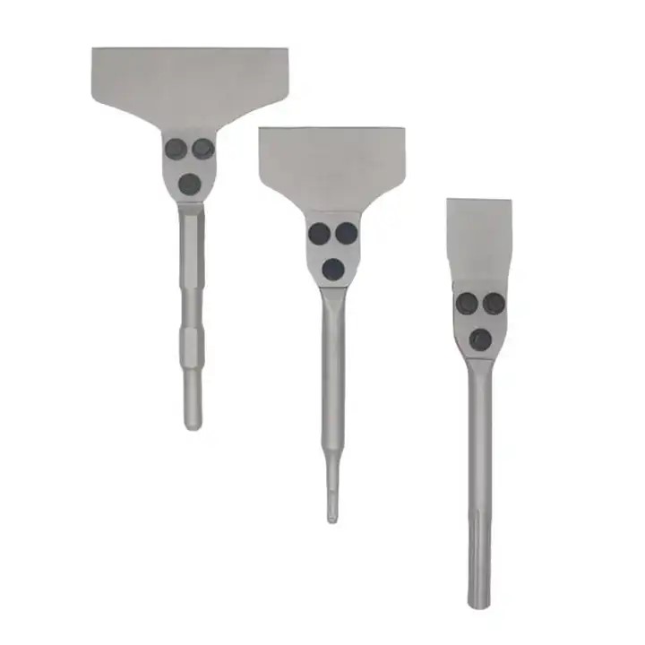
Flat shovels, slotted wall chisels, demolition points, clay spades, and floor scrapers are impact accessories rather than standard rotary drill bits. A tool-life rule based only on completed holes would therefore be unsuitable. Inspection should focus on cutting-edge rounding, deformation, cracking, bending, brazed-joint condition, shank wear, and secure engagement with the breaker or hammer.
An SDS Plus flat brazed shovel may be used for controlled channel or wall work, while an SDS Max chisel is suited to heavier concrete and stone operations. PH65A hex-shank demolition chisels and clay spades address breaking, hard-soil removal, and loose concrete. Floor-scraper tools with replaceable blades are evaluated through blade wear, fastening condition, working width, and the quality of thinset or tile removal. Keeping these categories separate prevents misleading comparisons and helps each tool perform within its intended range.
Conclusion
A reliable Drill Bit tool-life limit is not a single number that applies to every material or machine. It is a validated production range based on finished-hole requirements, stable installation, representative operating conditions, repeated trials, inspection intervals, and clear early-change signals. This approach makes replacement timing more predictable while reducing the risk of rough holes, excessive burrs, rising loads, unexpected breakage, and avoidable rework.
The same principle applies when selecting across different tool structures. SDS Plus electric hammer bits, high-quality three- or four-cutter electric hammer bits, and four-flute wood auger drill bits require different operating and wear criteria. Related tools such as SDS Plus flat brazed shovels, SDS Max concrete and stone chisels, 30 mm PH65A demolition chisels, PH65A clay spades, 17 mm A/F floor scrapers with replaceable blades, and 12-piece router bit sets should be evaluated according to their actual cutting or impact function rather than placed under one universal life figure.
Bestwin supports these application directions with drill bits, electric hammer bits, wood augers, router bits, chisels, spades, and removal tools for varied materials and equipment interfaces. Matching the tool structure to the work, then validating performance under real operating conditions, creates a more dependable basis for repeat production.










 English
  العربية
  Français
  Português
  Português do Brasil
  Italiano
  简体中文
简体中文  繁體中文
繁體中文  日本語
日本語  한국어
한국어  Deutsch
  Español
  Slovenčina
  ไทย
ไทย  Türkçe