
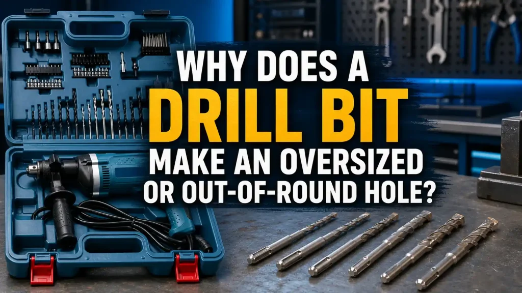
A hole can look clean at the surface and still fail a gauge, leave a fastener loose, or show an oval shape from the back. When the measured diameter is larger than the tool label, the first reaction is often to blame the cutter. The cause may instead be chuck runout, a bent shank, side pressure, an unstable workpiece, the wrong point geometry, or a measurement made before burrs are removed. A Drill Bit removes material through a rotating cutting edge, so any movement away from the intended axis becomes extra diameter. Finding the real source of that movement is the difference between replacing one tool and correcting a process that will spoil every hole.
Quick Answer
A Drill Bit makes an oversized or out-of-round hole when the cutting edges do not rotate on one stable centerline. Common causes include spindle or chuck runout, a bent bit, an incorrectly seated shank, unequal cutting lips, excessive feed, side loading, breakthrough grab, loose workholding, wrong speed, or a pilot hole that pulls the tool away from center.
Start by cleaning and measuring the hole, then check the Drill Bit, chuck, spindle, and workpiece separately. Rotate the tool by hand to look for wobble, reseat the shank, verify the cutting edges, clamp the work, and repeat the test in scrap material. A controlled comparison shows whether the problem follows the bit, the machine, the material, or the drilling method.
Define the Hole Error Before Correcting It
“Oversized” and “out of round” are related but not identical. An oversized hole may remain nearly circular while measuring larger than the nominal Drill Bit diameter. An out-of-round hole has different diameters across different axes. A bell-mouthed hole is wider near the entry. A tapered hole changes diameter through its depth. These shapes point toward different causes.
Do not judge only by fitting a bolt into the hole. Fasteners, pins, bushings, and anchors have their own tolerances. A loose fit may come from the fastener, burrs, coating removal, or a damaged edge. Measure the Drill Bit and the finished hole with tools suitable for the required accuracy. For ordinary workshop work, calipers may be enough. For close-tolerance production, pin gauges, bore gauges, or a defined inspection method may be necessary.
Remove loose chips and burrs before measuring. A burr can make an entry look smaller, while a torn edge can make it look larger. Check more than one direction and, when possible, more than one depth. A Drill Bit that produces a circular entry but an oval exit may be reacting to breakthrough rather than cutting oversized through the whole material.
Compare the Error With the Job Requirement
Not every hole needs precision machining tolerance. A clearance hole for a general bracket has different requirements from a dowel hole, anchor hole, rivet hole, or bearing location. The useful question is whether the Drill Bit produces a hole that meets the function. This keeps inspection practical and prevents a normal clearance feature from being treated as a failure.
If repeated holes change size during the same job, the process is unstable. Wear, heat, chips in the chuck, loosening workholding, or operator pressure may be changing over time. Record the first and later holes rather than examining only the worst one. That pattern often identifies the point at which the Drill Bit or setup began to move.
Table 1. Hole Shape and Likely Causes
| Hole condition | Common cause direction | First check |
|---|---|---|
| Circular but consistently oversized | Drill Bit diameter, runout, unequal lips, material springback | Measure bit, check runout, compare a second bit |
| Oval at entry and through depth | Side pressure, loose workpiece, chuck or spindle movement | Clamp work, support tool, inspect holder |
| Wide at entry and closer to size below | Poor centering, wandering start, unstable handheld angle | Use a center mark, guide, or controlled pilot |
| Circular at entry but rough or oval at exit | Breakthrough grab, unsupported material, excessive feed | Add backing support and reduce feed before exit |
| Tapered through the hole | Tool angle changes, long flexible bit, misaligned guide | Check alignment, bit length, and support |
| Multi-lobed or triangular appearance | Chatter, cutting-edge imbalance, resonant setup | Check cutting lips, speed, rigidity, and workholding |

Measure the Drill Bit Itself
The label or storage slot is not a measurement. Check the actual Drill Bit across the correct part of the cutting diameter. Coatings, wear, damage, sharpening, and manufacturing tolerance can change the effective size. A bit placed in the wrong tray can also create a simple but persistent error.
Inspect the cutting lips. On a conventional twist Drill Bit, the two main lips should be reasonably equal in length and angle. If one lip removes more material, the bit can rotate around a point that is not the geometric center. The hole may become oversized, lobed, or rough even when the shank runs true.
Look at the chisel edge and point. A damaged or uneven point can push the bit sideways during the start. A masonry Drill Bit with chipped carbide, a wood bit with a damaged spur, or a multipurpose bit with an uneven tip can all create different hole errors. The cutting geometry must suit both the material and the expected finish.
Check for a Bent Shank or Body
Roll a short straight Drill Bit on a known flat surface when that is an appropriate workshop check. A visible lift or changing gap suggests bending. For better evaluation, mount the bit and observe it at low speed or use an indicator where the process requires precision. Do not run a suspected bent bit at high speed.
Long bits are more flexible. Even a straight bit can deflect under side pressure or heavy feed. A long Drill Bit used for a shallow hole may create more movement than a shorter, more rigid option. Choose only the length needed for access and depth when accuracy matters.
Check Chuck and Spindle Runout
Runout means the rotating centerline moves around the intended axis. A small amount at the chuck can become a larger movement at the Drill Bit tip, especially with a long tool. Runout can come from dirt on the shank, uneven jaw tightening, worn jaws, a damaged arbor, spindle wear, or a poorly seated holder.
Remove the Drill Bit and clean the shank and chuck. A single chip between the shank and jaw can tilt the tool. Insert the bit far enough for secure clamping without catching the flutes in the jaws. Tighten the chuck evenly. On a keyed chuck, follow the tool maker’s method instead of tightening one hole carelessly and assuming the other jaw positions are equal.
Rotate the assembly by hand with the tool disconnected from power. Watch the shank close to the chuck and the tip farther away. If both wobble, the seating, chuck, arbor, or bit may be at fault. If the shank looks steady but the tip moves, the Drill Bit may be bent. If multiple known-straight bits show the same movement, inspect the machine rather than replacing each cutter.
Isolate the Source With a Simple Swap
Use a known-good Drill Bit of the same size in the same chuck. Then use the suspect bit in another known-good tool if the shop procedure allows it. If the error follows the bit, inspect geometry and straightness. If it stays with the machine, investigate the chuck, spindle, bearings, holder, and setup.
This swap is more reliable than changing several things at once. Replacing the bit, changing speed, moving the work, and using a different operator in one step may produce a good hole, but it does not identify the cause. A controlled test changes one variable and keeps the evidence useful.
Make Sure the Workpiece Cannot Move
An accurate rotating tool cannot make an accurate hole in a moving part. Thin sheet can lift into the Drill Bit. Round stock can roll. A small bracket can twist when the cutting lips engage. Wood can pull upward near breakthrough. Even movement that is difficult to see can enlarge the hole.
Clamp the work and support it near the drilling point. Use backing material where it helps control breakthrough and edge quality. On a drill press, secure the vise or fixture instead of holding it by hand. With a handheld drill, stabilize both the work and the operator’s position. The Drill Bit should advance along one axis without being used as a lever.
Workholding must match the material. Clamping thin sheet directly across a large unsupported gap can let it flex. A sacrificial backing plate can reduce distortion and burr formation. Tubes and curved sections may need a shaped support. A Drill Bit that enters a springy surface at an angle can cut an oval opening before it becomes aligned.
Control the Start of the Hole
Many oversized holes begin with an unstable start. A Drill Bit that skates across metal, follows wood grain, or enters a curved surface off-center removes material before the full diameter is established. Once the opening is enlarged, the tool cannot put the removed material back.
Use a center mark, center punch, guide bushing, template, or suitable starting technique for the material. The point should locate without creating a crater larger than the finished hole. For delicate surfaces, choose a method that controls position without damaging the coating or edge.
A pilot hole can help, but it must be sized and aligned correctly. If it is too large, the main Drill Bit may lose guidance at the center and chatter as the lips engage. If it is off-center, the larger bit may follow the error. If it work-hardens the material or creates a heavy burr, it can make the next cut less stable.
Use a Spotting Tool When Precision Requires It
For machine drilling, a short rigid spotting tool can establish the center more accurately than a long flexible jobber-length Drill Bit. The included angle and depth should support the following tool rather than forcing its cutting edges into an unsuitable seat. This is a process choice, not a universal rule for every handheld task.
When using a guide or jig, inspect the guide hole for wear. A worn bushing can allow the Drill Bit to enter at an angle even when the fixture looks correct. Repeated production holes should be checked at intervals so guide wear is found before a whole batch drifts out of tolerance.
Match Speed and Feed to the Diameter and Material
Excessive speed can heat the cutting edges, soften some materials, and increase chatter. Too little feed can make the Drill Bit rub rather than cut. Too much feed can flex the tool, pull the work upward, or make the bit grab at breakthrough. The right combination produces controlled chips and keeps the tool centered.
Large diameters generally need lower rotational speed than small diameters in the same material. Hard materials and hard cutting edges require their own recommendations. A Drill Bit designed for concrete with percussion behaves differently from a twist bit in steel or a brad-point bit in wood. Use the correct tool mode and cutting practice for the cutter.
Observe the chips. Consistent chips from both cutting lips suggest more balanced cutting. One strong chip and one weak chip may indicate unequal lip engagement, runout, or misalignment. Powder, discoloration, squealing, or repeated grabbing suggests that speed, feed, sharpness, or material match needs review.
The general Drill Bit concept covers many cutting geometries, and each geometry centers and clears chips differently. Hole accuracy improves when the bit style is chosen for the material instead of using one general cutter for every job.
Avoid Side Loading the Tool
A Drill Bit is intended to cut along its axis. Side pressure bends the bit and makes one edge sweep a wider path. Handheld drilling is especially sensitive because the operator may correct the angle while the tool is already engaged. The resulting hole can be wider at the entry, tapered, or oval.
Set body position before starting. Keep the drill aligned from two viewing directions when possible. Use a square, guide block, portable drill guide, or fixture when the hole angle matters. Do not use the Drill Bit to enlarge or straighten a hole unless the process specifically calls for a different cutting tool.
Side loading also occurs when chips pack in deep holes. The operator may pull the tool sideways while trying to clear it. Use controlled withdrawal and chip clearing. If the bit binds, stop rotation before forcing it free. A bent Drill Bit can continue producing oversized holes even after the original bind is forgotten.
Manage Breakthrough at the Back of the Material
As the point exits, the remaining material becomes thin and less able to guide the Drill Bit. The cutting lips may grab, pull forward, or tear the edge. Thin sheet can deform into a cone. Wood fibers can split. Brittle surfaces can chip. The entry may measure correctly while the exit looks oversized or irregular.
Reduce feed before breakthrough. Support the back face when appropriate. Keep the work clamped so the final cutting force does not lift it. For sheet metal, a step-style or other suitable cutter may give better control for some hole sizes, but the selection must follow the material, thickness, and finish requirement.
Do not measure across a torn exit and call the full bore oversized. Inspect the stable section of the hole and record the edge condition separately. A Drill Bit may be cutting close to size while the breakthrough method creates the visible defect.
Consider Material Behavior
Different materials respond differently after the cutting edge passes. Plastics can soften from heat and smear around the hole. Thin metal can distort. Laminated materials can delaminate. Wood grain can pull a bit sideways. Masonry can break around aggregate or weak edges. The Drill Bit and setup need to control the material rather than assuming every nominal diameter produces the same finished result.
In soft plastic, a conventional point may grab and pull through. Lower heat, suitable geometry, backing, and controlled feed can improve the hole. In thin metal, the bit may produce a multi-lobed shape because the sheet lacks support. In wood, a brad-point or auger-style Drill Bit can locate differently from a general twist bit.
Concrete and masonry require attention to percussion, carbide condition, and base-material variation. A chipped tip or hard aggregate can make the hole rough or oversized. However, a dedicated oversized-hole diagnosis should distinguish normal aggregate breakout from tool wobble. Measure several holes and compare locations before deciding the Drill Bit is the sole cause.
Check Tool Mode, Holder, and Accessory Compatibility
Hammer mode should not be used simply because drilling is slow. A Drill Bit intended for rotary cutting in metal or wood can produce poor holes or fail if the wrong impact mode is selected. Conversely, a masonry bit may need the correct hammer action in concrete. Match the tool, shank, holder, and mode.
SDS-plus, SDS-max, straight shank, hex shank, and other systems have different movement and retention characteristics. A Drill Bit must be fully seated and appropriate for the holder. Wear in an SDS system can permit movement that is normal for hammer action but unsuitable for a close-tolerance rotary hole. Do not compare hole accuracy across tool systems without considering their purpose.
Adapters add interfaces. Each interface can add runout or loosen under load. If a hole must be accurate, reduce unnecessary adapters and verify the assembled system. A premium Drill Bit cannot correct a damaged chuck, loose arbor, or unsuitable extension.
Diagnose Hand Drill and Drill Press Problems Differently
With a handheld drill, operator alignment, body position, and workholding are major variables. Repeat the hole with a guide or fixture. If accuracy improves, the Drill Bit may be acceptable and the process needs more support. A compact drill can also have more visible chuck movement than a rigid machine, especially with a long bit.
On a drill press, check table squareness, spindle play, chuck or taper seating, quill extension, and fixture stability. Extending the quill farther than necessary can reduce rigidity. A Drill Bit may run acceptably near the chuck and deflect when the quill and tool are both fully extended.
For production machinery, indicator measurements can separate spindle runout from tool runout. Check the spindle or reference surface, then the holder, then the Drill Bit shank and tip. The sequence matters because it prevents the bit from being blamed for movement introduced earlier in the stack.
Use a Structured Correction Test
After inspection, repeat the hole under controlled conditions. Use a known material sample, a secure clamp, a clean chuck, and a known-good Drill Bit. Mark the center carefully. Select suitable speed and feed. Measure the finished hole after deburring, then change only one variable if the error remains.
Useful comparisons include:
- Suspect bit versus known-good bit in the same tool.
- Same bit in a known-good second tool.
- Short bit versus unnecessarily long bit of the same diameter.
- Handheld drilling versus a supported guide.
- Existing workholding versus a rigid fixture with backing.
- Original speed and feed versus a recommended controlled setting.
This method turns an uncertain workshop complaint into a traceable result. A Drill Bit that passes in a rigid setup but fails in the original operation points toward alignment or workholding. A bit that fails in both setups is more likely damaged, unbalanced, bent, or incorrectly sized.
Read the Evidence in a Diagnostic Matrix
Table 2. Oversized Hole Diagnostic Matrix
| Evidence | Most likely direction | Corrective action |
|---|---|---|
| Every bit produces the same oversize in one machine | Chuck, spindle, holder, or measurement method | Check runout and calibration before replacing cutters |
| One Drill Bit produces the error in multiple tools | Bent body, wrong size, unequal lips, damaged point | Replace or professionally regrind as appropriate |
| Hole is accurate with a guide but not freehand | Operator angle or side pressure | Add alignment support and improve stance |
| Thin sheet shows lobed holes | Low rigidity, grabbing, unsuitable cutter or speed | Support sheet, adjust process, consider suitable geometry |
| Error grows as hole depth increases | Long flexible bit, misalignment, chip packing | Use shorter tool, improve guidance, clear chips |
| Exit is damaged but bore is near size | Breakthrough feed and backing | Reduce feed and support the back face |
| First holes pass and later holes fail | Heat, wear, loosening chuck, guide wear | Inspect intervals, cutting condition, and clamping |
The matrix should be used with actual measurements. Visual impressions are useful for direction, but the Drill Bit, hole, and rotating system need separate checks before a corrective action is approved.
Common Mistakes That Make the Hole Worse
The first mistake is using the spinning Drill Bit as a side-cutting reamer to enlarge or straighten the hole. This increases side load, damages cutting edges, and gives little control over final size. Use a process intended for finishing when tighter diameter or roundness is required.
The second mistake is tightening a dirty shank. Chips and oil can prevent even clamping. The third is clamping on the flutes. Chuck jaws should hold the shank area intended for clamping. A Drill Bit seated poorly can wobble even when it is straight.
The fourth mistake is pushing harder when the hole begins to chatter. More force can increase flex and grabbing. The fifth is measuring across burrs or torn fibers and treating that value as the bore diameter. Clean the hole and use a consistent inspection method.
The sixth mistake is replacing only the bit when several tools show the same error. Worn chucks, loose spindles, damaged adapters, and unstable fixtures can spoil new cutters quickly. A Drill Bit should be part of the diagnosis, not the automatic conclusion.
Choose a Replacement by the Real Failure Mode
If replacement is needed, select the Drill Bit by material, diameter, depth, shank, holder, cutting geometry, and required finish. A concrete hammer bit, wood auger, multipurpose bit, and metal twist bit solve different problems. The correct choice should remove material cleanly while remaining stable in the available tool.
For a bent or chipped bit, replacement is usually more reliable than trying to compensate with technique. For an unequally sharpened bit, professional regrinding may be appropriate in a controlled shop. For repeated oversize caused by the machine, a new Drill Bit will not solve the runout until the chuck or spindle is corrected.
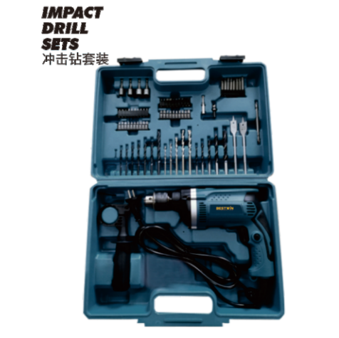
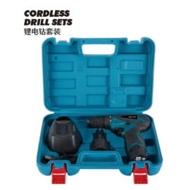
Bestwin offers drill-bit and drilling-tool options across hammer drilling and general workshop sets. After runout, workholding, alignment, speed, and material are checked, the relevant product can be matched to the actual tool system. That keeps selection connected to the hole requirement instead of using one cutter style for every material.
Final Takeaway
An oversized or out-of-round hole is evidence that the cutting path moved away from one stable axis. The cause can be the Drill Bit, but it can also be the chuck, spindle, holder, operator, workpiece, pilot, speed, feed, or breakthrough condition. Define the hole shape, measure after deburring, and isolate one variable at a time.
Clean and reseat the shank, inspect cutting-edge balance, check for bending, secure the work, control the start, reduce feed at breakthrough, and compare the result with a known-good setup. Once the cause is known, the Drill Bit can be replaced or matched to the material with confidence, while machine and process faults are corrected instead of being carried into the next hole.










 English
  العربية
  Français
  Português
  Português do Brasil
  Italiano
  简体中文
简体中文  繁體中文
繁體中文  日本語
日本語  한국어
한국어  Deutsch
  Español
  Slovenčina
  ไทย
ไทย  Türkçe