

On a stainless steel tube line, the first holes in a new run may look acceptable while later parts show blue heat marks, a widening exit burr, or a polished spot where the cutting edges have begun to rub. The operator may not change the machine program, yet hole quality moves because the tool, tube wall, support, lubrication, and breakthrough condition are interacting.
A Drill Bit for repeat tube production has to be matched to that complete cutting situation. Diameter alone cannot describe the required point geometry, tool material, working length, shank, edge preparation, or batch control. For distributors, OEM programs, fabricators, and equipment builders, the useful manufacturing question is how those details remain consistent from approved sample to repeat shipment.
Réponse rapide
A Mèche controls heat and exit burrs in stainless steel tube production when its substrate, point geometry, lip symmetry, web thickness, flute finish, edge condition, working length, and shank are matched to the tube grade, wall thickness, machine, speed range, feed stability, support, and coolant method. The approved result then needs a retained sample, dimensional record, material traceability, functional cutting test, and defined replacement limit.
Bestwin fabrique des outils de forage et fournit des programmes OEM et par lots à partir de sa propre gamme de produits. La nuance du tube du client, le diamètre, la paroi, la taille du trou, l'interface machine, l'objectif de cycle, la pratique de refroidissement, l'emballage et le volume de commande donnent à Bestwin la base pour faire correspondre une direction de foret appropriée et préparer des échantillons. Ce processus maintient le rôle de l'usine clair : la preuve d'application guide la correspondance du produit, tandis que le fabricant contrôle la spécification de l'outil et la production répétée.
Heat Marks Are a Process Signal, Not a Color Specification
Heat color around a hole can reveal rising cutting temperature, but it does not identify a single cause. A worn edge may rub instead of shear. A feed interruption may dwell the Drill Bit against work-hardened material. A long unsupported tool may vibrate. Weak tube support may let the wall move during breakthrough. Insufficient or poorly directed coolant may leave the cutting zone hot even when fluid is present elsewhere.
L'investigation utile compare où la couleur apparaît, quand elle commence dans la durée de vie de l'outil, et ce qui arrive à la forme du copeau et à la hauteur de la bavure en même temps. La chaleur concentrée au point suggère un mécanisme différent de celui d'une marge polie ou d'un anneau bleu uniquement du côté de la sortie. Si la charge de la broche augmente progressivement sur un lot, l'usure de l'arête est plus probable qu'une erreur aléatoire de position du tube. Si la marque apparaît soudainement après une interruption, un écrouissage du matériau peut être impliqué.
Un examen d'échantillon de foret commence donc par des pièces et des enregistrements, et non par des suppositions. Bestwin peut évaluer les outils neufs et usagés, les photographies de trous, les échantillons de copeaux, les bavures mesurées, les comptes de cycles et les conditions de la machine. L'objectif est d'identifier quelles caractéristiques d'outil nécessitent un contrôle et quelles conditions de production doivent rester dans la fenêtre de validation du client.
Tube Grade and Wall Condition Define the Cutting Event
Stainless steel is not one uniform workpiece. Austenitic grades, ferritic grades, welded tube, seamless tube, annealed material, work-hardened zones, and surfaces with scale or coating can respond differently. Wall thickness changes the time that both cutting lips remain engaged and the way the material releases at breakthrough. Tube curvature changes the entry contact, while a seam can create a local change in hardness or geometry.
For the tool manufacturer, the application description is strongest when it includes the material standard or grade, hardness when available, tube outside diameter, nominal and tolerance wall thickness, seam location, surface condition, hole diameter, positional tolerance, and whether the hole crosses one wall or both walls. A short cut sample is often more valuable than a generic statement such as “for stainless steel.”
Power and rigidity also vary with the machine. A hand-held drill, dedicated tube machine, machining center, and automatic fixture do not create the same feed stability. The Drill Bit specification must reflect the actual interface rather than an ideal laboratory spindle. Bestwin uses those conditions to decide which material, geometry, length, and shank direction deserves a functional sample.
Table 1. Stainless steel tube symptom and evidence map
| Production symptom | Possible cutting mechanism | Evidence that separates the causes |
|---|---|---|
| Blue mark at the entry | Dwell, rubbing edge, insufficient local coolant | Feed trace, edge photograph, chip color, coolant direction |
| Burr grows only at the exit | Weak support, low feed at breakthrough, worn corner | Fixture condition, breakthrough feed, burr height trend |
| Le trou devient trop grand | Runout, long overhang, unequal lips, tube movement | Tool runout, lip measurement, fixture deflection, hole roundness |
| Short curled chips become stringy | Edge wear, flute loading, changing feed | Chip samples by cycle count, spindle load, flute condition |
| Sudden squeal and load spike | Work-hardened spot, chip packing, unstable engagement | Part location, seam position, audio/load record, removed tool inspection |
| Acceptable sample but variable batch | Material or geometry inconsistency, mixed machine conditions | Material certificate, lot record, tool dimensions, controlled cutting test |
This evidence map prevents every symptom from being assigned to coating or hardness. A Drill Bit can only be evaluated fairly when the cutting condition and the result are recorded together.
Point Geometry Controls Entry, Centering, and Load Balance
The point is the first part of the tool to meet the curved tube surface. Its angle, chisel edge, split-point form, relief, and lip symmetry influence how quickly the tool centers and how evenly both sides begin cutting. On a curved wall, an unstable entry can produce an eccentric mark before the full diameter is engaged.
Bestwin matches Mèche des échantillons autour du trou du client et des conditions de la machine. Une géométrie qui fonctionne bien dans un montage rigide peut ne pas être la meilleure direction pour un outil portable avec plus de faux-rond. Une pointe plus courte peut modifier la séquence de percement dans les parois minces, tandis qu'une âme plus épaisse peut améliorer la résistance mais augmenter la poussée si l'arête de ciseau n'est pas préparée de manière appropriée.
Lip symmetry matters across the batch. If one lip is longer or carries a different relief, that side removes more material and can pull the Drill Bit off center. The result may be heat on one margin, an oversized hole, uneven chips, or a burr concentrated on one side. Point inspection therefore belongs with the cutting test rather than as a separate cosmetic check.
For OEM orders, the drawing or released specification can define the geometry features that affect performance, together with a functional reference sample. The drawing creates a measurable boundary; the sample shows how the complete Drill Bit behaves in the intended tube and fixture.
Substrate, Heat Treatment, and Surface Condition Work Together
Tool material provides the base hot hardness and toughness, but the material name alone is not a performance guarantee. High-speed steel and cobalt-bearing high-speed steel directions can suit different duty levels, diameters, machine stability, and cost targets. Heat treatment must develop the intended structure consistently, and grinding must avoid damaging the finished edge.
A Drill Bit that is very hard but too brittle for the actual runout or interrupted engagement can chip. A tougher tool that loses edge strength at temperature can begin rubbing and generate more heat. Bestwin reviews the application and sample evidence to balance those properties rather than presenting one material label as universally superior.
Surface treatment or coating can reduce friction or change wear behavior, but it cannot compensate for unstable feed, poor runout, weak support, or incorrect geometry. Coating thickness and edge preparation also matter because a small cutting edge can be altered by an inconsistent layer. The factory control plan should connect substrate, heat treatment, grinding, surface condition, and the final cutting result.
Every Drill Bit in an approved family needs a consistent identity. Material lot records, heat-treatment records, dimension checks, surface inspection, and functional samples make it possible to trace a change instead of debating it after mixed results appear in production.
The Machine Interface Can Overrule a Good Cutting Edge
Runout at the tool tip increases the load on one lip and changes the effective hole diameter. The source may be the shank, chuck, spindle, adapter, contamination, or tool overhang. A good Drill Bit installed in an unstable interface can produce the same symptoms as a poorly ground tool.
The sample plan therefore records shank form, chuck or holder, measured runout, unsupported length, spindle condition, and the clamping method used for approval. If the customer later changes from a drill press to a portable cordless tool, or from one holder to another, that change deserves confirmation because the mechanical boundary has moved.
Tool length is part of the interface. Extra length can provide access but reduces stiffness. In stainless tube work, avoidable deflection can increase rubbing during entry and make breakthrough more abrupt. The Drill Bit working length should cover the real fixture and tube geometry without adding unsupported reach that the application does not need.
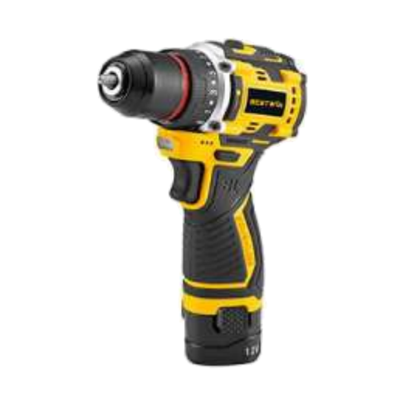
For distributor kits or OEM maintenance sets, the tool interface also affects assortment design. A kit may combine bits and a cordless drill, but the approved content still needs compatible shanks, useful size progression, and a documented application range. Bestwin can supply individual tools or matched sets, while the project specification identifies which items are qualified for the stainless tube operation.
Breakthrough Is Where Exit Burrs Are Created
At entry, the tube wall supports the cutting zone around the point. Near exit, the remaining material becomes thin and less able to resist deformation. Feed instability, tube movement, excessive runout, or a worn corner can push and tear the final material instead of cutting it cleanly. The Drill Bit may still reach the target diameter while leaving an unacceptable burr.
Burr control begins with a stable fixture and a repeatable breakthrough condition. The tool geometry, edge condition, machine feed, wall thickness, backup support, and hole position all influence the result. A production test that reports only “hole completed” misses the feature that may create the next assembly problem.
Measure burr height or another agreed acceptance characteristic at defined positions and cycle counts. Photographing the exit side under the same lighting makes trend comparison easier. If the burr rises with spindle load and chip color, the Drill Bit is probably moving toward its replacement limit. If the burr changes by tube orientation with a new tool, fixture or seam effects deserve attention.
The broad mechanics of a Mèche help describe the tool, but factory approval needs application-specific evidence. Stainless tube breakthrough is a combined event, so material, machine, support, and tool records remain linked in the test report.
Coolant Delivery and Chip Evacuation Affect the Wear Curve
Coolant information needs more detail than “wet” or “dry.” Fluid type, concentration, delivery point, flow consistency, and the ability to reach both lips affect temperature and chip movement. A stream that hits the outside of the tube but not the cutting zone may give little protection during deep engagement.
Chip form is a practical process record. Chips that suddenly discolor, become long and stringy, or pack into a flute can show that cutting has changed before hole size moves outside tolerance. The Drill Bit flute surface, helix, web, edge condition, and feed all contribute to chip behavior.
In a factory sample, Bestwin can inspect the tool after a defined number of holes while the customer records chips, cycle time, spindle load, and hole results. This shared evidence separates product wear from an uncontrolled coolant or machine change. It also creates a more realistic replacement limit than waiting for visible failure.
For batch supply, the coolant and chip condition from the approved test becomes part of the reference method. A Drill Bit lot should not be rejected or approved against a different process without documenting the difference, because the test would no longer represent the released application.

Sample Approval Must Include the Wear Trend
A new tool can make several good holes even when its edge, heat treatment, or geometry will not support the required production interval. Sample approval should therefore cover the beginning, middle, and planned end of the cycle. The number of holes depends on the application, but the record needs enough duration to reveal heat growth, edge wear, chip change, burr development, and dimensional movement.
The customer provides the machine, tube, fixture, coolant, and acceptance criteria. Bestwin provides identified Drill Bit samples, manufacturing information appropriate to the order, and a consistent sample lot. Both sides use the same test method so that the result can guide a released specification rather than remain an informal demonstration.
The retained tool and part samples are especially useful. A used Drill Bit shows wear location and failure mode, while cut tube sections show entry, bore, and exit conditions. Keeping samples from different cycle points makes the wear trend visible and gives the factory a reference if a later lot behaves differently.
This is the stage where a Drill Bit manufacturer can connect product engineering with batch reality. Bestwin can adjust or match material, geometry, length, shank, surface condition, marking, and packaging within the agreed program, then submit a new sample when a controlled change requires confirmation.
Batch Consistency Is Built Into the Released Identity
Repeat orders need more than the same printed description. The released Drill Bit identity can include item code, drawing revision, material direction, critical dimensions, point geometry, shank, finish, marking, packaging, inspection plan, and approved functional test. Those elements prevent a familiar name from hiding an uncontrolled change.
Drill Bit Suppliers may describe products with broad categories such as HSS, cobalt, twist, coated, or jobber length. For a stainless tube program, the operational identity must be more specific. For a buyer evaluating a Drill Bit supplier, that specificity makes a sample and repeat batch comparable. Bestwin links the order to the approved sample and manufacturing record so the factory knows which characteristics and checks support the expected result.
Incoming material control, heat-treatment monitoring, grinding inspection, surface review, dimensional sampling, runout checks, and final functional testing each protect a different part of the result. No single certificate replaces them all. A stable Drill Bit lot emerges when these controls point to the same released specification.
Packaging also preserves the edge. Contact between tools, loose movement, moisture exposure, and poor cavity fit can damage a correctly manufactured product before it reaches the line. Bestwin can match individual packs, sets, labels, and export packaging to the project, while the approved pack remains part of the batch identity.
Inspection Connects Dimensions With Cutting Performance
Dimensional inspection is essential, but a complete release also asks whether the tool behaves correctly in material. Diameter, total length, working length, shank, point geometry, lip symmetry, runout, surface condition, and marking can be checked before cutting. A defined tube test then verifies entry, load, chip formation, hole size, roundness, heat mark, and exit burr.
Table 2. Drill Bit sample and batch release record
| Control point | Sample-stage evidence | Repeat-batch evidence |
|---|---|---|
| Identité du produit | Drawing, item code, approved sample | Purchase order and revision match |
| Material and heat treatment | Material direction and hardness record | Lot traceability and process record |
| Geometry | Point, lips, web, flute, length and shank measurements | Sampling results against released limits |
| Surface and edge | Coating or finish review, edge photographs | Visual inspection and controlled process record |
| Mechanical fit | Holder compatibility and tool-tip runout | Shank and runout sampling |
| Functional result | Controlled stainless tube cutting test | Defined lot sample test with matching conditions |
| Emballage | Approved protection, label and cavity layout | Pack audit and shipment traceability |
The table is most useful when each line has an acceptance limit and an owner. A Drill Bit can pass dimensions and still fail the application if the edge or process is wrong; it can also cut well in an uncontrolled one-off test that cannot be reproduced. Pairing the two evidence types produces a defensible release.
A Useful RFQ Describes the Tube, Machine, and Target
An effective RFQ gives Bestwin enough information to match a Drill Bit without forcing the customer to design the tool independently. Include the stainless grade or representative sample, tube diameter and wall, hole diameter and tolerance, expected burr limit, entry and exit condition, machine type, holder, speed and feed range, coolant method, fixture support, desired holes per tool, annual volume, packaging, labeling, and required standards.
Si la commande est destinée à la distribution plutôt qu'à une ligne de production, décrivez le principal champ d'application et les marchés desservis. Les fournisseurs de forets pourront alors proposer une gamme de tailles contrôlée ou une famille de produits sans prétendre qu'une seule géométrie couvre toutes les nuances d'acier inoxydable et toutes les machines. L'usine de Bestwin peut préparer des échantillons et des informations produit à l'appui du périmètre défini.
Changes also need a route. A different tube grade, wall thickness, machine, holder, or coolant practice may change the result even when the part number stays the same. The project record can state which changes require a new trial and which fall inside the approved window.
Stable Stainless Tube Holes Depend on Controlled Evidence
Heat marks and exit burrs become manageable when the production record connects the tube, fixture, machine, coolant, chips, tool wear, and hole result. The Drill Bit is central to that system, but its performance is meaningful only within a defined application window.
Bestwin can match Mèche produits pour échantillons de tubes en acier inoxydable après examen du matériau, de la paroi, du diamètre, de l'interface machine, de la durée de vie cible, de l'emballage et des besoins de lot du client. De la préparation de l'échantillon à la fabrication, en passant par les tests, le marquage OEM et l'approvisionnement répété, l'usine peut maintenir l'identité de l'outil libéré connectée à la preuve qui l'a approuvé.









 English
  العربية
  Français
  Português
  Português do Brasil
  Italiano
  简体中文
简体中文  繁體中文
繁體中文  日本語
日本語  한국어
한국어  Deutsch
  Español
  Slovenčina
  ไทย
ไทย  Türkçe