
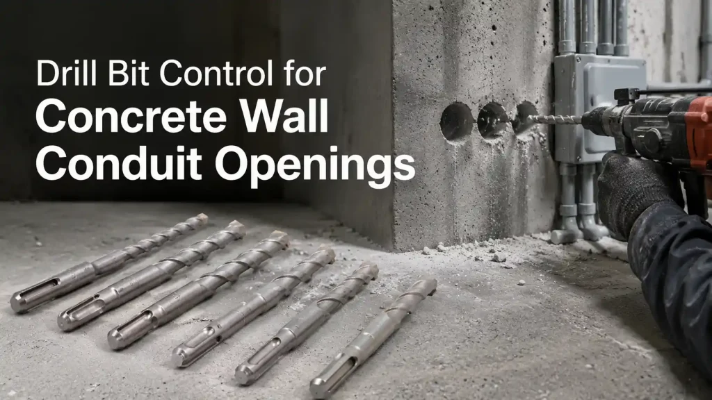
A conduit opening through a concrete wall may be only one line on an electrical drawing, yet it can interrupt installation when the bore wanders, fills with compacted dust, breaks the far face, or stops at hard aggregate. The visible entry is only part of the result. The sleeve, cable, or small pipe also needs a clear path through the full wall thickness. At Bestwin, we manufacture hole-making tools for contractors, distributors, OEM programs, and project supply, and we match each Drill Bit direction to the concrete condition, opening diameter, drilling depth, rotary-hammer interface, and finished-hole requirement.
Schnelle Antwort
A Bohrer produces a dependable concrete wall conduit opening when the cutting head, flute volume, shank, working length, rotary hammer, impact energy, alignment, dust-clearing method, and breakthrough control operate as one system. The tool must advance through changing aggregate without losing its axis, move dust out of a deep bore, and reach the far face without uncontrolled breakout.
The practical route is to define the finished opening first, scan the drilling zone, test the proposed Drill Bit on representative concrete, and record progress rate, dust behavior, hole geometry, exit condition, and wear. Bestwin uses those application details to match and manufacture a suitable product direction, then connects the accepted sample to the dimensions, marking, inspection, and batch identity used for supply.
A Conduit Opening Has More Requirements Than Diameter
The nominal diameter normally comes from a conduit, sleeve, cable bundle, or sealing component. The finished opening, however, also has an axis, usable length, edge condition, clearance, and position relative to reinforcement and nearby services. A round entry can hide a bore that curves inside the wall. A generous diameter can still fail if the far end is offset enough to interfere with a sleeve or box connection.
Wall thickness changes the meaning of a size request. A short fixing hole gives the Drill Bit little distance in which to deviate. A through-hole across a thick wall magnifies small errors at the start, at the chuck, or along the tool body. If a sleeve must pass straight through, the permitted entry-to-exit offset matters as much as diameter. If the route only carries flexible cable, the geometric limit may be different, but sharp internal steps and loose concrete still need attention.
The two wall faces can have different finish limits. One side may be hidden above a ceiling while the other remains visible in a finished room. The exit may open behind a panel, near a corner, or beside an existing penetration. Bestwin asks customers to identify the entry and exit faces of the workpiece, as this affects the required drill bit length, drilling method, exit-side support, and sample acceptance criteria.
The service passing through the wall defines the evidence
A rigid metal sleeve reveals alignment error immediately because it cannot follow a curved bore. Flexible conduit tolerates more offset but may snag on an internal ridge. Fire-stopping and weather-sealing systems may require a stable annular space around the service. The article does not replace a project specification; it shows why the tool sample must reproduce the opening that the assembly actually needs.
Concrete Changes From the Surface to the Far Face
Concrete is not a uniform block. Paste, sand, coarse aggregate, local voids, reinforcement, embedded items, and repair material can all appear along one drilling path. A Drill Bit may advance quickly through mortar and then slow at a hard stone particle. If the operator responds only by increasing force, the tool can deflect, polish the contact, overload the rotary hammer, or pack more dust into the bore.
Reinforcement and hidden services require a separate decision. Scanning and project controls belong before drilling begins. A Drill Bit that encounters reinforcement is not an instruction to continue through it. Cutting a bar or changing the route can affect the structure and requires authorization from the responsible project professionals. The tool record should state whether the sample is for plain concrete, reinforcement-free zones, or another specifically approved condition.
The Rotary Hammer, Shank, and Drill Bit Form One Drive System
The cutting head cannot work independently of the machine. Rotary speed turns the edges through the concrete, while the impact mechanism helps fracture the mineral structure. The shank transfers both actions and permits the designed movement inside the tool holder. A mismatch at any interface can reduce energy transfer, increase vibration, or damage the connection.
SDS Plus and other shank systems are not interchangeable labels. The selected interface must fit the intended rotary hammer, diameter range, working length, and load. Tool-holder wear, contamination, insufficient lubrication where the equipment instructions require it, or a damaged retention groove can make a good Drill Bit run poorly. The chuck and shank condition should be recorded during testing so that interface problems are not blamed on the cutting head.
Machine capacity also sets a realistic boundary. A Bohrer should be selected together with the declared tool holder, machine class, diameter, and depth. A suitable cutting head cannot compensate for an incompatible rotary hammer or a worn holder.
For procurement and sample release, shank form, body length, flute pattern, and cutter style should be recorded as one configuration. Changing any one of these variables can alter energy transfer, handling, dust removal, or finished-hole quality.

Cutter Head Geometry Controls Contact and Stability
The head starts the fracture pattern and guides the bore. A worn, chipped, asymmetrical, or poorly centered head can make the Drill Bit wander or create an opening larger than expected. In hard aggregate, the load may move between cutting points as the head crosses material with different resistance. A balanced design helps the tool maintain a more stable axis under those changing contacts.
Two-cutter and multi-cutter directions can behave differently, but the number alone is not a performance guarantee. Head diameter, carbide grade, brazing quality, symmetry, edge condition, body support, and machine energy all contribute. Bestwin reviews these characteristics against the actual wall, hole size, and equipment rather than presenting one head count as universally correct.
The connection between the carbide and steel body is especially important under impact. Visual inspection can reveal cracks, missing material, irregular seating, or damage after an abnormal event. Dimensional checks confirm that the maximum cutting diameter and body remain within the agreed range. A Drill Bit sample should be inspected before and after the test so that changes can be connected to the drilling record.
Table 1. Concrete Wall Condition and Sample Evidence
| Wall or drilling condition | Auswirkung auf den Schnitt | Evidence to record | Product implication |
|---|---|---|---|
| Thick, dense wall | Small alignment errors grow over the full depth | Entry-to-exit offset, bore clearance, drilling time | Working length, body straightness, stable head geometry |
| Large or hard aggregate | Progress and impact response change locally | Slowdown points, vibration, cutter condition | Carbide direction, head support, machine compatibility |
| Reinforcement-free scanned route | The planned path avoids unauthorized bar cutting | Scan record, marked position, completed path | Concrete-cutting direction without unsupported rebar claims |
| Finished far face | Breakthrough damage remains visible | Exit photograph, chip boundary, sleeve fit | Breakthrough method and remaining-length control |
| Overhead or angled access | Gravity changes dust return and operator control | Dust extraction behavior, alignment, tool handling | Flute clearing, length, machine and accessory fit |
| Repeated project holes | Wear and setup variation accumulate | Hole sequence, time trend, diameter, head wear | Inspection interval, batch identity, replacement trigger |
Flutes Must Move Dust Across the Entire Working Length
Concrete dust occupies space. In a shallow hole it may leave quickly, while in a deep path it travels along the flutes for much longer. If the bore becomes packed, impact energy is absorbed by debris and friction rises along the body. Progress slows even though the head still turns. Continuing without correcting the condition can heat the tool, enlarge the bore, and increase load on the rotary hammer.
Flute geometry, usable length, bore clearance, orientation, and extraction method influence dust flow. More visible dust outside the opening does not automatically mean the deepest part is clear. The sample should include controlled withdrawal or clearing intervals when the project method requires them. Those intervals are part of the process record, not an improvised rescue action after the Drill Bit has already stalled.
Overhead work changes the route taken by debris. Dust can fall toward the tool holder and the operator, so suitable extraction, personal protection, and site controls are essential. Horizontal wall drilling can allow material to settle along the lower part of the bore. An inclined route may create another pattern. Bestwin matches the Drill Bit direction using the stated orientation because a vertical bench test cannot represent every field position.
Working length needs its own acceptance limit. Adding length changes stiffness, dust travel, machine load, handling, packaging, and the evidence needed for release; it should not be treated as a simple extension of the same configuration.

Starting Accuracy Determines the Final Exit Position
A deep opening begins with a few millimeters of contact. If the Drill Bit starts at an angle, walks across a coating, or enters a poorly marked position, the error remains through the wall. A rigid guide, stable stance, perpendicular reference, or suitable drilling fixture can control the first stage. The chosen method depends on access and project equipment, but it must be repeatable during the sample.
Surface render, paint, tile, or another facing can change the start. The outer layer may require its own controlled approach before the concrete receives impact. The tool direction must be compatible with both the visible surface and the structural material behind it. Bestwin records these layers so the Drill Bit sample does not prove only an exposed laboratory block when the project starts through a finished wall.
Alignment needs periodic confirmation during a long cut. Excessive side force can bend the body or wear the bore unevenly. A very long extension arrangement can magnify runout and handling error. If an extension or adapter is part of the installation method, the complete stack should appear in the test record, including its connection and straightness.
Breakthrough Needs Less Force and Better Position Awareness
The final section of concrete becomes less supported as the cutter approaches the far face. If full feed force continues, the remaining material can break away in a large cone. That damage may exceed a cover plate, reduce support around a nearby fixing, or leave an irregular edge for sealing. The Drill Bit process needs a way to recognize remaining depth and reduce the severity of breakthrough.
Wall thickness measurements, depth marks, stops, machine travel, and a controlled feed change can help. The useful method depends on equipment and access. A depth mark on the body is only meaningful if the reference surface and tool engagement are consistent. Drilling time by itself is unreliable because aggregate changes the progress rate.
A Controlled Sample Connects the Tool to the Application
The most useful sample reproduces the intended diameter, depth, orientation, concrete type, rotary hammer, and clearing method. It begins with an identified tool and a documented setup. Each hole then records whether the Drill Bit starts accurately, advances without abnormal intervention, clears debris, maintains a usable bore, and reaches the exit inside the agreed damage boundary.
This is where Bestwin’s experience as a drill bit manufacturer supports a more detailed sample evaluation. We can compare the head geometry, carbide condition, body straightness, shank dimensions, flute design, and post-test wear with the actual hole results. This helps us develop a drill bit sample around the specific concrete, drilling conditions, and acceptance requirements rather than assuming that one construction will perform equally well in every concrete wall.
Drill Bit Suppliers may show similar diameters in a catalog, but a project record needs more specific identity. The accepted sample should connect diameter, total length, working length, shank, head direction, surface condition, marking, package label, and revision status. That connection lets incoming inspection and repeat orders refer to the same configuration that produced the accepted opening.
Table 2. Concrete Conduit Opening Sample Record
| Aufnahmeartikel | What Bestwin or the project team provides | Warum es wichtig ist |
|---|---|---|
| Conduit, sleeve, or cable requirement | Outside dimension, clearance, seal or fire-stop interface | Defines usable bore size and edge condition |
| Wall construction | Thickness, strength information when available, aggregate notes, surface layers | Keeps the sample tied to representative material |
| Scanned route | Approved position and known reinforcement or service restrictions | Prevents the tool test from implying permission to cut hidden elements |
| Rotary hammer setup | Model or machine class, holder, mode, condition, accessories | Separates machine behavior from Drill Bit behavior |
| Werkzeugidentität | Diameter, lengths, shank, head style, batch or sample code | Preserves traceability from test to supply |
| Drilling method | Orientation, guide, feed approach, dust clearing, extraction | Makes the successful process repeatable |
| Finished-hole evidence | Entry, exit, offset, sleeve fit, internal obstruction, photographs | Confirms the opening performs its installation function |
| Wear evidence | Hole count, time trend, cutter and body inspection | Establishes an inspection or replacement trigger |
Batch Supply Must Preserve the Accepted Geometry
A good prototype does not finish the work. Repeat production must preserve the characteristics that controlled the sample. Bestwin can connect material control, carbide placement, brazing or joining checks, body straightness, shank dimensions, surface treatment, marking, and final inspection to an approved Drill Bit identity. The control level is matched to the project, order volume, and risk of a mixed configuration.
Measurement does not need to turn every shipment into a laboratory report. It needs to cover the characteristics that matter to the opening. Diameter and length may be direct receiving checks. Head condition, symmetry, shank form, marking, packaging separation, and sample comparison can support batch release. When a design or production detail changes, revision control prevents an unrecorded substitution from entering a repeat order.
This is also where Drill Bit Suppliers differ in practical support. A useful supply conversation links the product to the concrete, machine, depth, orientation, quantity, packaging, and inspection evidence. Bestwin supports OEM marking, project quantities, controlled samples, and repeat batch supply where those details are agreed, without turning an application article into a promise of identical performance in every wall.
Als Lieferant von Betonbohrern kann Bestwin die Identität der akzeptierten Probe in die Kennzeichnung, die Verpackungstrennung, die Mengenplanung und die Wiederholproduktion übernehmen. Diese Kontrollen halten die kommerzielle Bestellung mit der getesteten Anwendung verbunden, ohne die Baustellenmethode des Auftragnehmers oder die Autorität des Projektmanagers zu ersetzen.
Rotary-hammer compatibility should be verified with the same care as bit geometry. The holder, operating mode, available impact energy, diameter, working length, and application conditions should be documented before the sample is released.
Diagnose a Slow or Damaged Hole From the Evidence
When progress drops, replacing the Drill Bit immediately may remove the symptom without identifying the cause. The location and timing of the change are useful. A slowdown at nearly the same depth in adjacent holes may point to a material band or reinforcement zone. A gradual increase in time across many holes may indicate wear or reduced clearing. Sudden vibration after a jam may justify inspection of the head, body, shank, and tool holder.
The finished bore adds another layer of evidence. A consistently oversized entry may come from starting movement or guide clearance. Offset at the far face may involve initial angle, body deflection, machine runout, or side loading. Heavy breakout can involve remaining-depth control and feed. Polished dust or very limited debris movement can indicate rubbing or packing. The Drill Bit is evaluated together with the machine and method so that corrective action addresses the real source.
General references describe the many forms and uses of a Bohrer, but the relevant evidence for a concrete conduit opening remains application-specific. The wall, tool, rotary hammer, orientation, and finished service path must agree.
Useful stop signals include visible carbide damage, a bent body, abnormal shank wear, repeated jamming, a significant time increase, unacceptable diameter, excessive offset, or exit damage beyond the project limit. A Drill Bit that reaches depth but no longer produces an acceptable opening has reached its practical limit for that job.
Project Information Keeps Matching Efficient
Project teams can shorten sample work by providing the actual opening and equipment conditions at the start. The information does not need to be a complex purchasing document. A marked drawing, wall description, service dimension, rotary-hammer model, target quantity, and photographs of both wall faces often reveal the main boundaries.
The most useful details are:
- The finished opening diameter, wall thickness, and permitted entry-to-exit offset are stated.
- The conduit, sleeve, cable bundle, or sealing component is identified.
- The wall material, surface layers, drilling orientation, and scanned route are described.
- The rotary hammer, holder, operating mode, adapters, and access limits are recorded.
- The acceptable entry and exit damage, dust-control method, and site restrictions are defined.
- The sample quantity, expected hole count, packaging, marking, and repeat-order needs are included.
With that information, Bestwin can match a Bohrer family, prepare a controlled sample, and connect the accepted result to the required supply record. The final recommendation still depends on the concrete, depth, holder, machine energy, orientation, and finished opening.
Schlussfolgerung
A reliable concrete wall conduit opening comes from a matched system: a stable cutting head, effective flutes, a correct shank, a compatible rotary hammer, accurate starting, controlled dust clearing, and careful breakthrough. The decisive proof is a representative sample that produces the required path through the full wall, not an attractive entry alone.
Bestwin manufactures and supplies drilling tools for project, distributor, OEM, and repeat-order needs. By reviewing the wall, opening, machine, access, sample evidence, and batch requirements together, the factory can keep the selected Drill Bit connected to the real conduit installation without overstating what one tool can do in every concrete condition.










 English
  العربية
  Français
  Português
  Português do Brasil
  Italiano
  简体中文
简体中文  繁體中文
繁體中文  日本語
日本語  한국어
한국어  Deutsch
  Español
  Slovenčina
  ไทย
ไทย  Türkçe