
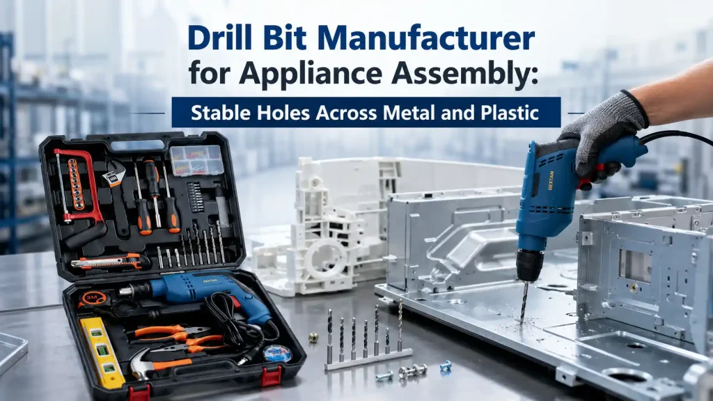
Home-appliance factories may drill thin painted steel, stainless brackets, aluminum supports, molded plastic parts, and service panels within one production program. The hole looks simple, but material thickness, curvature, fixture support, machine interface, chip control, finish protection, and batch replenishment all affect the cutting tool. Bestwin approaches the drill bit as a controlled production item: the product family, diameter, geometry, surface condition, packaging, and acceptance evidence must match the station. This gives appliance OEMs and contract assemblers a practical route from drawing review to sample approval and repeat supply without pretending that one tool or one cutting condition suits every material.
Quick Answer
Choose a drill bit for appliance assembly only after grouping holes by workpiece material, thickness, diameter, tolerance, finish, depth, machine, holder, and production volume. Separate thin-sheet fastener holes, reinforced-bracket holes, plastic pilot holes, and larger circular openings because they need different product and test conditions. Give the manufacturer representative parts or material coupons, then compare samples using agreed speed, feed, fixture, lubrication, entry quality, exit burr, diameter, roundness, chip behavior, cycle time, and wear limit. Freeze the accepted specification, label, pack quantity, and reorder code so the approved tool can be reproduced across later batches and different plants.
Why Appliance Assembly Needs a Controlled Drill Bit Program
An appliance production line is not one drilling application. A refrigerator cabinet, washing-machine housing, air-conditioning enclosure, oven panel, or small-appliance chassis can combine sheet metal, local reinforcements, plastic liners, aluminum pieces, brackets, and purchased subassemblies. The same nominal hole size may appear in materials that behave differently at entry, during chip formation, and at breakthrough.
Thin sheet is especially sensitive to support and breakthrough. The workpiece can flex as the drill bit approaches the exit, producing a raised burr, distorted hole, or sudden grabbing action. A reinforced area may be thicker and more stable but create more heat. Painted or coated sheet adds a finish requirement: the operation must limit scratching, chipping, and discoloration around the hole.
Plastic parts create another boundary. A cutting edge that pushes or rubs can generate heat, whitening, cracking, or a rough exit. Some molded parts have ribs, curved faces, or varying wall thickness. The drill bit must be tested in the actual polymer and geometry because a result from one plastic cannot be assumed for another.
Production volume turns these differences into a supply question. If operators compensate for inconsistent tools by changing pressure or adding unrecorded steps, cycle time and hole quality drift. If a replacement batch arrives under the same generic description but has different point geometry or diameter control, the approved process may no longer be valid. A controlled program links each station to a defined product, sample record, and replenishment code.
South American appliance producers and contract manufacturers may also use a mixture of automated fixtures, drill presses, pneumatic tools, and portable drills across more than one facility. The goal is not to force every plant into one assortment. It is to identify where the same drill bit can be standardized and where material, holder, or operating conditions require a separate item.
Table 1. Appliance-Assembly Hole Groups
| Hole group | Typical workpiece condition | Product information to define | Sample acceptance focus |
|---|---|---|---|
| Sheet-metal fastener hole | Thin painted, galvanized, or stainless panel | Diameter, point geometry, cutting material, coating, shank | Low walk, controlled burr, limited finish damage |
| Reinforced bracket hole | Thicker steel or stacked material | Total thickness, hardness, interrupted entry, depth | Straightness, heat control, chip evacuation, edge condition |
| Aluminum support hole | Soft nonferrous material with possible chip adhesion | Alloy or representative sample, depth, lubrication boundary | Clean flute evacuation, diameter stability, limited built-up edge |
| Molded-plastic pilot hole | Curved or ribbed polymer wall | Resin, wall thickness, support, through or blind condition | No cracking, melting, whitening, or excessive exit breakout |
| Vent, cable, or service opening | Larger circular feature in sheet or panel | Diameter, cut depth, arbor or holder, pilot arrangement | Roundness, slug removal, edge quality, interface fit |
| Rework and maintenance hole | Variable access with portable equipment | Material range, chuck capacity, pack format, lower-volume sizes | Correct item identification and practical station control |
Divide the Hole Drawing into Purchasable Tool Families
Start with the drawing, process sheet, or station list. Mark each hole by material, thickness, diameter, tolerance, and function. Then add the machine, holder, production frequency, and whether the operation is automatic, fixture-guided, or hand-held. This turns a long drawing into several repeatable drill bit purchasing groups.
Small fastener and pilot holes
A conventional twist drill bit is often the first candidate for screw, rivet, locator, and clearance holes in metal. The final choice still depends on steel condition, point geometry, cutting material, finish, and machine rigidity. Small holes can be sensitive to runout, point symmetry, and chip packing, so diameter alone is not a complete order description.
For molded plastic, the same basic tool form may be considered only after testing. Sharp edges and controlled cutting can reduce rubbing, but feed, support, wall thickness, and polymer behavior remain important. A plastic pilot-hole item should have its own approval record even when its nominal diameter matches a metal-hole item.
Reinforced and stacked sections
Local brackets, hinge supports, motor mounts, or frame joints can place two layers under the tool. The drill bit may encounter a gap between layers, an edge, a weld zone, or a different material. State the complete stack rather than only the top-sheet thickness. The sample check should look for chip trapping, hole misalignment between layers, sudden breakthrough, and damage at the interface.
Larger circular openings
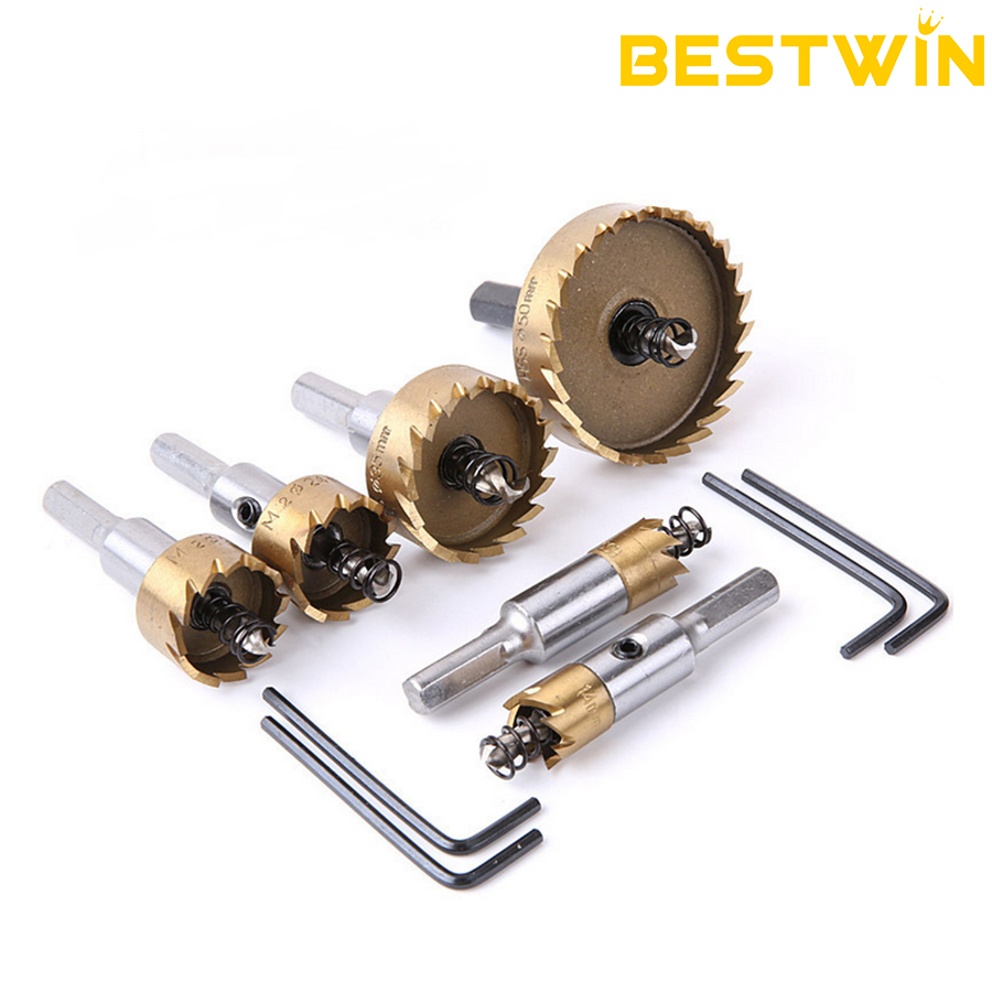
Cable entries, service ports, sensor mounts, and ventilation features may be too large for an ordinary twist tool. A suitable hole saw or another approved cutting tool can remove an annular path instead of the full diameter. It should be specified separately by cutting diameter, cutting depth, tooth or edge material, arbor connection, pilot arrangement, and workpiece condition.
Calling every round cutter a drill bit creates procurement errors. The factory should retain the product-family distinction even when the items share a kit or supplier. That makes replacement parts, pilots, arbors, and acceptance limits easier to control.
Rework and low-volume stations
Portable stations often need a compact range rather than the full automated-line inventory. The pack should contain only the sizes and interfaces the station can use. A large assortment can look convenient, but unused pieces raise cost and make it easier for an operator to select an unapproved size. A controlled kit with clear labels, protected edges, and an inventory list is more useful.
Match Cutting Material and Geometry to the Workpiece
The drill bit product decision is a combination of cutting material, heat treatment, geometry, surface condition, and dimensional control. No single label proves performance. The appliance drill bit supplier should connect those characteristics to the customer’s workpiece and test result.
High-speed steel and tougher alloys
High-speed steel is widely used for general rotary drilling because it can provide a practical balance of hardness and toughness. For more demanding steel or higher heat, a cobalt-bearing grade may be considered when the machine, holder, and process are suitable. The alloy name should be supported by the complete product specification and sample evidence, not treated as a stand-alone guarantee.
Carbide constructions offer different wear and stiffness characteristics. They can be useful in controlled applications but are less tolerant of impact, misalignment, or flexible hand-held setups. An automated fixture and a portable rework station may therefore need different drill bit choices for the same nominal diameter.
Point geometry and entry control
Point angle, lip symmetry, chisel-edge form, web thickness, and split-point treatment influence how the tool centers and how much thrust it needs. On a finished panel, walking at entry can damage the coating before the hole is formed. On thin material, excessive thrust can distort the wall near breakthrough.
A centering geometry can help, but fixture rigidity, runout, surface curvature, and operator handling still affect the result. The sample should use the real entry face and support. A flat laboratory coupon alone may not represent a production part that is curved or ribbed.
Flute form and chip movement
Flutes create space for chips and help carry them out of the hole. Their form, finish, length, and helix interact with material and depth. In sheet metal, long flutes may be unnecessary and can reduce rigidity. In a deeper reinforced stack, inadequate chip space can increase rubbing and heat. In aluminum or plastic, chip adhesion can change both surface finish and withdrawal.
The drill bit length should be no longer than the station needs. Excess reach increases deflection and runout at the point. State the working length and access constraint rather than ordering the longest available item by habit.
Surface finish and coating
Bright, black-oxide, or coated tools can behave differently in friction, chip release, corrosion resistance, and wear. The coating must be compatible with the tool substrate and application. Colour is not reliable proof of coating composition or quality. Keep the approved surface condition in the purchase specification and inspect it as part of incoming identity.
For a neutral reference on the basic parts and categories of a drill bit, the general technical overview is useful. Appliance qualification still depends on the selected product data, the actual material, and the factory’s own acceptance results.

Control Diameter, Runout, Shank, and Holder Fit
Drill bit hole quality is produced by the tool-and-machine system. A drill bit can meet its own diameter requirement and still cut oversize if it runs out in a worn chuck, enters on a curved surface, or has unequal cutting lips. The approval therefore needs product measurements and a repeatable station condition.
Define the dimensional requirement
State nominal diameter, permitted tool tolerance where relevant, required finished-hole range, and any roundness or positional concern. The tool tolerance and hole tolerance are related but not identical. Machine runout, fixture movement, material springback, and burr measurement can change the observed hole.
Measure the drill bit using the agreed method, then record the finished hole using the method appropriate to the drawing. If a go/no-go gauge is used on the line, include the same gauge logic in the sample. If the hole receives a rivet, screw, grommet, or cable gland, fit testing may provide a useful functional check alongside dimensions.
Inspect symmetry and straightness
Unequal cutting lips can make one edge remove more material, causing an oversized or lobed hole. A bent shank or body can add runout. Visual inspection, suitable gauges, and functional sampling help screen these issues. The inspection method should suit the product size and risk; it should not create a complicated laboratory routine with no connection to production.
Specify the shank and holder
Round, hexagonal, reduced, or other shank forms fit different tools and use cases. Record the shank type, diameter, usable length, and holder capacity. A diameter that fits one drill press may not fit a compact rework chuck. A hex shank may aid retention in a compatible holder but should not be assumed where a different interface is specified.
Check the actual chuck or holder condition during approval. Worn jaws, contamination, insufficient insertion, or poor tightening can make a good drill bit slip or run out. The product supplier can define the shank; the appliance factory controls holder maintenance and operating practice.
Keep the station record stable
The approval record should name the machine or station, holder, fixture, workpiece, speed range, feed method, lubrication boundary, and operator instructions used. When a tool moves to another plant or station, compare those conditions before assuming the previous result transfers unchanged.
Test Samples on Real Metal and Plastic Parts
A disciplined drill bit test does not need excessive complexity. It needs representative material, a fixed setup, visible acceptance limits, and enough repetition to compare candidates. As an appliance drilling tool supplier, Bestwin matches product direction and provides sample packaging options after the material and station data are available, but the customer should make the final production approval under its own process conditions.
Step 1: confirm sample identity
Record the supplier, product description, diameter, cutting material, geometry, surface condition, shank, lot or sample code, and packaging. Photograph the new edge and label. If several candidates look similar, assign temporary test numbers so observations are not mixed.
Step 2: establish the station condition
Check holder cleanliness and runout, fixture support, workpiece orientation, backing arrangement, and chip-clearance path. Set speed, feed method, and lubrication according to the approved trial plan. Use the same condition for each comparable sample unless the purpose is to optimize a parameter separately.
Step 3: evaluate entry and breakthrough
Watch how the drill bit starts, whether it walks, the force needed to cut, chip form, sound, and behavior at exit. Inspect the entry for coating damage or plastic whitening. Inspect the exit for burr height, tearing, breakout, melting, or distortion. Measure the hole and perform any required fastener or fitting check.
Step 4: repeat through a meaningful interval
One clean hole only proves that the new sample can make one clean hole. Continue through an interval relevant to the line and inspect at planned points. Record cycle time, machine load where available, edge condition, hole size, burr, and any operator adjustment. The goal is to establish a replacement or inspection trigger based on quality, not to promise a universal hole count.
Step 5: test the difficult variant
Include the thickest stack, hardest material, least supported shape, curved entry, or most finish-sensitive part that belongs to the intended product scope. A drill bit approved only on the easiest coupon can fail when production reaches the real limiting condition.
Step 6: retain passing and failing evidence
Keep representative parts, photographs, measurements, and notes from both successful and rejected trials. A failed sample can be valuable because it shows which symptom belongs to the tool, setup, or material. The evidence helps engineering investigate a later change without relying on memory.
Table 2. Drill Bit Sample and Repeat-Supply Approval
| Approval item | Sample-stage evidence | Batch-stage control | Requalification trigger |
|---|---|---|---|
| Product identity | Diameter, material, geometry, finish, shank, label | Incoming label and visual check | Description, label, or construction change |
| Dimensional result | Tool measurement, finished-hole range, functional fit | Agreed dimensional or fit sampling | Trend outside control limit or new hole tolerance |
| Edge and surface quality | Entry, exit burr, coating damage, plastic condition | Visual standard and retained examples | New material, finish, or repeated surface defect |
| Cutting behavior | Speed, feed, cycle time, chips, heat, operator notes | Periodic functional sampling | Machine, holder, fixture, or process change |
| Wear limit | Inspection points and rejection symptom | Replacement or inspection instruction | Unexplained life reduction or changed volume |
| Packaging and identification | Pack quantity, edge protection, labels, reorder code | Carton and unit-pack inspection | Shipping method or pack-format change |
| Traceability and change control | Sample or lot reference, approved specification | Lot code and supplier notification | Critical manufacturing or material change |
Turn the Approved Drill Bit into Repeatable Production Supply
The approved drill bit must be easy to order correctly. Create an internal code for each material-and-station combination, not just each diameter. Two 5 mm tools may need different records if one is approved for stainless brackets in a drill press and the other for plastic pilot holes in a portable fixture.
Record material, hole, machine, volume, packaging, and destination data
Send the workpiece material or a representative sample, thickness or stack, hole drawing, required quality, machine and holder, expected volume, desired pack quantity, target destination, and test method. If the customer wants one product to cover several materials, list every material and identify the limiting case. The appliance drill bit supplier can then tell whether one sample direction is credible or separate items are needed.
Commercial information matters because it affects packaging and production planning. State trial quantity, expected annual volume, order frequency, destination market, private-label need, barcode or language requirement, and preferred carton format. These details should not replace technical information, but they should arrive before the final quotation.
Link the reference sample to manufacturing controls
As an appliance tool manufacturer, Bestwin converts the accepted drill bit diameter, material, geometry, heat-treatment direction, surface condition, shank, markings, and packaging into an order reference. Inspection should concentrate on characteristics that affect fit, cutting behavior, identification, and transport protection. The exact control plan depends on the product family and agreed specification.
The customer should retain the approved sample or a documented equivalent. When later batches are reviewed, the comparison should use the same workpiece and station condition. If results move, both teams can investigate material, equipment, fixture, operator, storage, and tool variation instead of blaming one factor automatically.
Plan packaging for the line and shipment
Cutting edges need protection from impact and contact during international transport. Packs should resist confusion between nearby diameters and make lot or order identity visible. In humid or long-storage conditions, the agreed corrosion protection and packaging barrier should be maintained without contaminating the customer’s process.
For South American distributors or multi-plant manufacturers, carton labeling may need item code, diameter, quantity, lot, country information, and customer-specific language or barcode. Confirm these requirements during sample approval. Repacking at destination can break traceability if unit packs and outer cartons do not share a controlled reference.
Control replenishment by consumption
High-use diameters can be packed for convenient line replenishment, while low-use items can remain in smaller protected quantities. Track usage by station and workpiece rather than treating every replacement as equal. A sudden increase may indicate harder material, holder runout, changed cutting conditions, or a batch issue.
The category overview for drill bit products can start the discussion, but the inquiry should identify the exact appliance materials and holes. That keeps the quotation focused on relevant samples, approved sizes, and repeat supply instead of an oversized assortment.
Prevent the Most Common Selection and Purchasing Errors
The first error is ordering by diameter alone. A 6 mm drill bit for painted sheet, a 6 mm item for stainless reinforcement, and a 6 mm item for plastic may need different constructions or process limits. Add material, thickness, station, and acceptance information.
The second error is approving only a flat coupon. Curved panels, unsupported sheet, ribs, stacked parts, and finish-sensitive surfaces can behave differently. Test the limiting production geometry.
The third error is changing speed, feed, lubricant, or fixture while comparing samples. That makes it impossible to tell whether the drill bit or the process caused the result. Fix the condition, record it, and change one variable at a time when optimization is needed.
Another error is using a premium material label as the whole specification. Alloy, coating, or carbide terminology does not replace geometry, dimensional control, heat treatment, surface quality, and sample performance. Purchase the complete approved product.
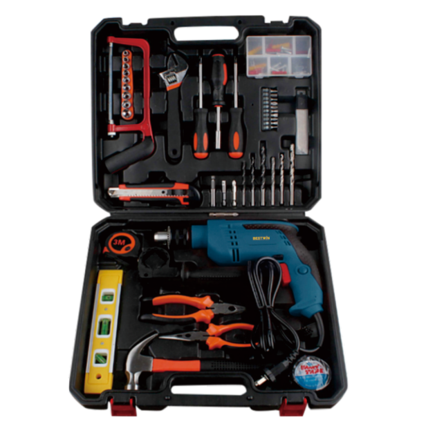
Large mixed kits can also create hidden waste. If a rework station uses only five sizes, a 100-piece assortment may add unrelated items and weak identification. Match the kit to the station, protect the edges, and label each replacement path.
Factories sometimes accept the first batch but fail to retain the sample code, photographs, test condition, or packaging standard. The next order then starts from memory. A short approval pack is more valuable than an elaborate report that production cannot use.
Finally, not every hole problem is a supplier defect. Holder runout, loose fixtures, material variation, worn machines, blocked chips, and undocumented operating changes can produce the same symptoms. A good drill bit manufacturer helps define product evidence, while the appliance factory keeps the station evidence needed for a fair diagnosis.
Conclusion
Reliable appliance drilling begins by separating the work into material-and-station groups. Define the hole, select the product construction, confirm holder fit, test real parts, document the wear and quality limits, and preserve the approved identity. That approach makes each drill bit a controlled consumable instead of an interchangeable item chosen only by diameter.
Bestwin supports appliance OEMs, assemblers, and distributors as a drill bit manufacturer with sample matching, product-family selection, specification control, packaging discussion, and repeat-order coordination. When the inquiry includes representative metal and plastic conditions, we can focus the quotation and test plan on the tools that matter to production, then carry the accepted requirements into later supply.
Frequently Asked Questions
Can one drill bit be approved for steel, aluminum, and plastic?
Possibly, but only when each material falls within the product scope and passes its own representative test. The same nominal diameter does not prove common suitability. Record separate acceptance limits and station conditions for every material.
What should an appliance factory send for sample matching?
Send drawings or hole lists, material specifications or coupons, thickness, coatings, plastic resin where known, machine and holder details, speed and feed boundary, annual volume, packaging need, and photographs of the difficult entry or exit condition.
How should burr acceptance be defined?
Use the product drawing, downstream assembly need, and a repeatable inspection method. A visual reference, measured limit, or functional fitting test can work when clearly agreed. Apply the same method to all samples and later batches.
Does a coated drill bit always last longer?
No. Coating benefit depends on substrate, adhesion, geometry, cutting temperature, workpiece, and operating condition. A coated item should be compared under the intended process and approved as a complete product.
When is a hole saw more appropriate than a twist tool?
A suitable hole saw can be practical for larger circular openings because it removes an annular path. Confirm diameter, depth, edge material, arbor, pilot, machine, support, and slug removal. It remains a separate product family with its own approval.
How can drill bit suppliers support repeat orders?
They can preserve the agreed product code, manufacturing specification, label, packaging, inspection basis, lot reference, and change-notification process. The customer supports repeatability by keeping the approved sample and station conditions stable.










 English
 العربية
 Français
 Português
 Português do Brasil
 Italiano
 简体中文
 繁體中文
 日本語
 한국어
 Deutsch
 Español
 Slovenčina
 ไทย
 Türkçe